
Schema overview
This document explains the components of a property graph schema and shows you how to create and manage a graph schema.
Graphs let you model connected data that represents information as a network of nodes and edges. A graph schema consists of nodes and edges, along with labels that classify type their type, and properties that describe them. You define a property graph schema by mapping rows from input tables to graph nodes and edges and defining custom labels and properties. To learn more about BigQuery Graph, see the BigQuery Graph overview.
Understand the property graph data model
A property graph lets you model connected data as a network of nodes and edges. Nodes represent entities in your data, such as customers, products, or locations. Edges represent connections between those nodes, capturing relationships such as purchases, follows, or locations.
Nodes and edges can include the following information:
Labels: classify nodes and edge types. For example, students in a class might have a
Studentlabel and aPersonlabel. If you don't explicitly define a label for a node or an edge, BigQuery Graph uses the input table name as the default label.Properties: used to describe nodes and edges. For example, a node that represents a person might have a
nameproperty with the valueAlexand anidproperty with the value1.
The example in Figure 1 shows how you might design a graph to model financial activities. This graph includes the following types of entities modeled as nodes:
- Person: represents an individual involved in financial transactions.
- Account: represents a bank account used for transactions.
These entities are connected by different types of relationships, which are represented by the following directed edges:
- Owns: a person owns one or more accounts.
- Transfers: money moves from one account to another.
Each directed edge indicates a one-way relationship that flows from a source
node to a destination node. For example, a Transfers edge connects a source
Account to a destination Account, indicating the flow of money.
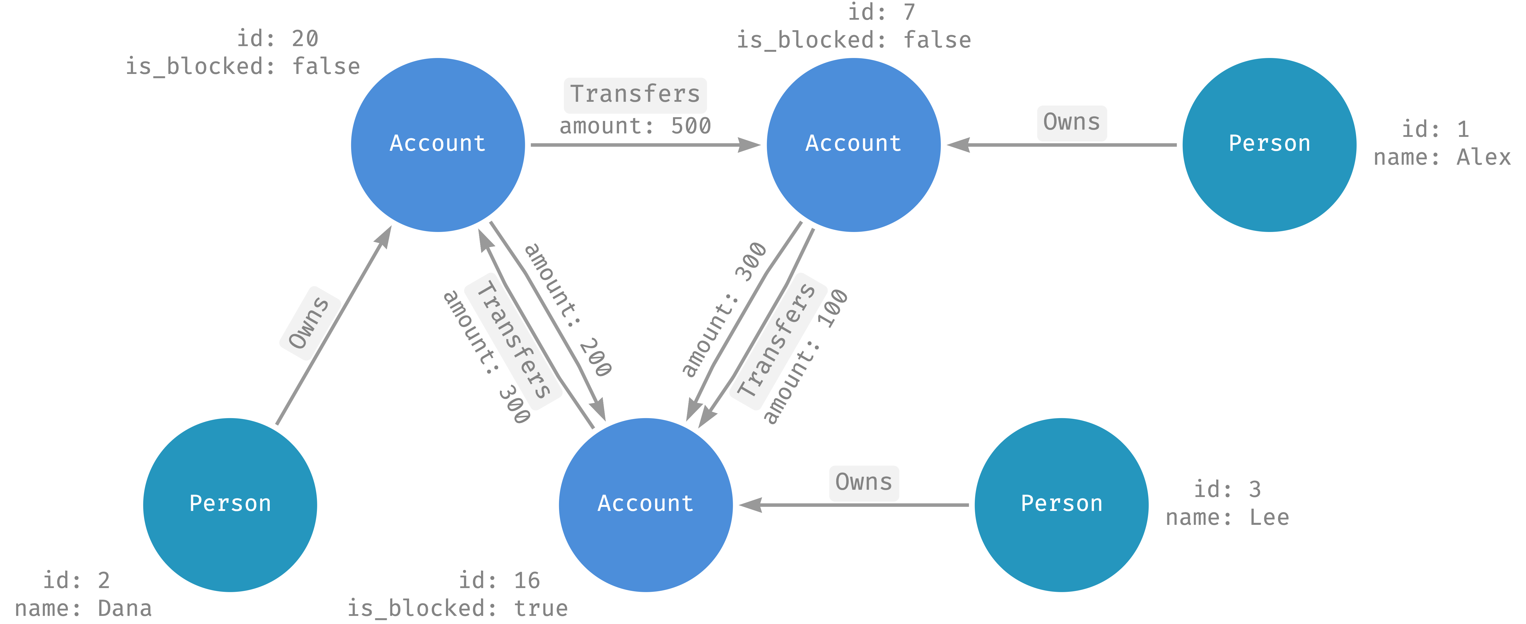
Figure 1. Example graph with multiple nodes and directed edges.
Nodes and edges include additional information in properties.
Personnodes include these properties:name(STRING)id(INT64)
Transfersedges include this property:amount(FLOAT64)
Directed and undirected edges
Directed edges indicate a specific direction in the relationship between entities. For example, a person owns an account, but an account doesn't own a person. However, some relationships, like the friend relationship in a social network, are undirected and represent a reciprocal connection. In this case, you can model undirected edges as two directed edges, one edge in each direction.
Design your schema
BigQuery Graph lets you use the
CREATE PROPERTY GRAPH
statement to create a graph from tables. The tables that create graphs are
called input tables.
Define a node
Nodes are defined by rows in tables.
To define a node, add a node definition in the
NODE TABLES clause.
The simplest form of a node definition contains the name of an input
table with a primary key.
BigQuery Graph maps rows from the input
table to graph nodes.
In the following example, you use the
NODE TABLES clause
to define the Account node in the FinGraph property graph. The node
definition contains the input table Account.
-- Create an Account table.
CREATE TABLE graph_db.Account (
  id           INT64 NOT NULL,
  create_time  TIMESTAMP,
  PRIMARY KEY (id) NOT ENFORCED
);

-- Use the Account table as the input table for the Account node definition.
CREATE PROPERTY GRAPH graph_db.FinGraph
  NODE TABLES (
    graph_db.Account
  );
By default, BigQuery uses the table name as the label and exposes all columns from the input table as properties.
- Each account node uses the
Accountlabel. - Each account node includes
idandcreate_timeproperties from theAccounttable columns.
Element key
A node definition also defines the element key, a collection of columns
that uniquely identifies a
graph node. By default, the element key is the primary key of the input table.
Alternatively, you can use the KEY clause to explicitly define element keys.
The following example defines an Account node and a Person node. The
Account node uses the Account table's primary key as its element key.
The Person node explicitly specifies the id column as the element
key by using the KEY clause.
CREATE TABLE graph_db.Person (
  id           INT64 NOT NULL,
  name         STRING
);

CREATE TABLE graph_db.Account (
  id           INT64 NOT NULL,
  create_time  TIMESTAMP,
  PRIMARY KEY (id) NOT ENFORCED
);

CREATE PROPERTY GRAPH graph_db.FinGraph
  NODE TABLES (
    graph_db.Person KEY (id),
    graph_db.Account
  );
- Each row with a non-null element key maps to a unique node in the graph identified by the element key.
- Rows with a null element key are ignored.
The same input table can be used in multiple node definitions. In this case, a given row in the input table maps to one node for each node definition.
Define an edge
Edges are defined by rows in tables.
To define an edge, add an edge definition to the
EDGE TABLES clause.
The simplest form of edge definition contains the name of an input table and
defines source and destination node references.
BigQuery Graph uses this definition to map rows from the
input table to graph edges.
By default, BigQuery uses the table name as the label and exposes all columns from the input table as properties.
- Each edge's element key is defined in the same way as nodes.
Source and destination node references
An edge definition defines the source and destination node reference by using
the SOURCE KEY, DESTINATION KEY, and REFERENCES clauses.
You must define the source and destination nodes before using them in the
edge definition.
In the following example, you create a property graph FinGraph with the
following:
PersonandAccountnodesPersonOwnAccountedge
CREATE TABLE graph_db.Person (
  id            INT64 NOT NULL,
  name          STRING,
  PRIMARY KEY (id) NOT ENFORCED
);

CREATE TABLE graph_db.Account (
  id            INT64 NOT NULL,
  create_time   TIMESTAMP,
  PRIMARY KEY (id) NOT ENFORCED
);

CREATE TABLE graph_db.PersonOwnAccount (
  id            INT64 NOT NULL,
  account_id    INT64 NOT NULL,
  create_time   TIMESTAMP,
  FOREIGN KEY (account_id) REFERENCES graph_db.Account (id) NOT ENFORCED,
  PRIMARY KEY (id, account_id) NOT ENFORCED
);

CREATE PROPERTY GRAPH graph_db.FinGraph
  NODE TABLES (
    graph_db.Person,
    graph_db.Account
  )
  EDGE TABLES (
    PersonOwnAccount
      SOURCE KEY (id) REFERENCES Person (id)
      DESTINATION KEY (account_id) REFERENCES Account (id)
  );
Each PersonOwnAccount edge connects a Person (source) node to an Account
(destination) node.
- The source node of an edge is a
Personnode where theidproperty is the same as the edgeidproperty. - The destination node of an edge is an
Accountnode where theidproperty is the same as the edgeaccount_idproperty. - The element key is the primary key of the
PersonOwnAccounttable, namely(id, account_id). - Each edge has the same set of properties as the columns from the
PersonOwnAccounttable. - Each edge has the default
PersonOwnAccountlabel.
Map rows to edges
Each row in the edge input table with a non-null element key typically maps to a single edge in your graph. However, if the source or destination node reference matches zero or more nodes in the source or destination node table, then the row in the edge input table could result in zero or multiple edges in your graph.
Define nodes and edges within a single table
You can define a node and its incoming or outgoing edges in a single table if your table's columns define a relationship to another table. This approach reduces the number of tables, simplifies data management, and can improve query performance by eliminating the need for a join to a separate edge table.
For example, if the following Account table has a composite primary key
(owner_id, account_id), the owner_id column can be a foreign key that
references a Person table. This structure allows the Account table to
represent both the Account node and the incoming edge from the Person node.
CREATE TABLE graph_db.Person (
  id INT64 NOT NULL,
  PRIMARY KEY (id) NOT ENFORCED
);

-- Assume each account has exactly one owner.
CREATE TABLE graph_db.Account (
  owner_id INT64 NOT NULL,
  account_id INT64 NOT NULL,
  FOREIGN KEY (owner_id) REFERENCES graph_db.Person(id) NOT ENFORCED,
  PRIMARY KEY (owner_id, account_id) NOT ENFORCED
);
You can use the Account table to define both the Account node and its
incoming Owns edge. This is shown in the following CREATE PROPERTY GRAPH
statement. In the EDGE TABLES clause, you give the Account table the alias
Owns. This is because each element in the graph schema must have a unique
name.
CREATE PROPERTY GRAPH graph_db.FinGraph
  NODE TABLES (
    graph_db.Person,
    graph_db.Account
  )
  EDGE TABLES (
    graph_db.Account AS Owns
      SOURCE KEY (owner_id) REFERENCES Person
      DESTINATION KEY (owner_id, account_id) REFERENCES Account
  );
Customize labels and properties
You can use the
LABEL
and
PROPERTIES
clauses to customize labels and properties.
The following example defines a Person node with a custom property
and an Account node with multiple labels:
CREATE TABLE graph_db.Person (
  id               INT64 NOT NULL,
  name             STRING,
  birthday         TIMESTAMP,
  country          STRING,
  city             STRING,
  PRIMARY KEY (id) NOT ENFORCED
);

CREATE TABLE graph_db.Account (
  id               INT64 NOT NULL,
  create_time      TIMESTAMP,
  is_blocked       BOOL,
  nick_name        STRING,
  PRIMARY KEY (id) NOT ENFORCED
);

CREATE PROPERTY GRAPH graph_db.FinGraph
  NODE TABLES (
    graph_db.Person KEY (id)
      LABEL Customer
      PROPERTIES (CONCAT(city, ", ", country) AS address)
      LABEL Entity PROPERTIES (id, name),
    graph_db.Account KEY (id)
      LABEL Account PROPERTIES (id, create_time)
      LABEL Entity PROPERTIES (id, nick_name AS name)
  );
The
Personnodes use theCustomerlabel to expose theaddressproperty. Theaddressproperty is defined by the expressionCONCAT(city, ", ", country),that refers to thecityandcountrycolumn from the input tablePerson.The
Accountnode uses theAccountlabel to expose theidandcreate_timeproperties.
The Person and Account nodes both have the Entity label with properties
id and name.
- In the
Personnode, theidandnameproperties come from the input table columns. - In the
Accountnode, thenameproperty refers to thenick_namecolumn of the input table.
Label and property consistency
In a graph, labels and properties are uniquely identified by their names. You can use labels and properties with the same name in multiple node or edge definitions. However, labels and properties with the same name must follow these rules:
- Properties with the same name must use the same value type.
- Labels with the same name must expose the same list of properties.
In the previous example, the Entity label is defined in both the Person and
Account nodes. Both definitions include the same set of property names, id
and name, with identical value types.
Manage schema dependencies
Graphs depend on the schema of the input tables to the node and edge definitions, and the table columns referenced by the properties. BigQuery Graph doesn't check whether deleting or altering tables or columns invalidates an existing graph schema.
You are responsible for avoiding breaking schema changes. Follow these best practices:
- Before you delete a table used in a graph node definition, first remove that node definition from the graph.
- Before you remove a column from a table that is exposed as a property in a graph, remove the property from the corresponding node or edge definition.
View graph schemas
You can visualize your graph schema in a notebook.
Update a graph schema
To make any change to an existing graph's schema, you must redefine the
graph schema by using the CREATE PROPERTY GRAPH statement.
Delete a graph schema
To delete a property graph, use the
DROP PROPERTY GRAPH statement.
What's next
- Learn more about BigQuery Graph.
- Learn how to create and query a property graph.
- Learn about graph schema best practices.