
TPU v5p
This document describes the architecture and supported configurations of Cloud TPU v5p.
System architecture
This section describes the system architecture specific to the v5p version. Each TensorCore has four Matrix Multiply Units (MXU), a vector unit, and a scalar unit.
There are 8960 chips in a v5p Pod. The largest job that can be scheduled is a 96 cube (6144 chip) job.
The following table shows the key specifications for TPU v5p.
| Specification | Values |
|---|---|
| Number of chips per pod | 8960 |
| Peak compute per chip (BF16) (TFLOPs) | 459 |
| Peak compute per chip (FP8) (TFLOPs) | 459 |
| HBM capacity per chip (GiB) | 95 |
| HBM bandwidth per chip (GBps) | 2765 |
| Number of vCPUs (4-chip VM) | 208 |
| RAM (GB) (4-chip VM) | 448 |
| Number of TensorCores per chip | 2 |
| Number of SparseCores per chip | 4 |
| Bidirectional inter-chip interconnect (ICI) bandwidth per chip (GBps) | 1200 |
| Data center network (DCN) bandwidth per chip (Gbps) | 50 |
| Interconnect topology | 3D torus * |
Configurations
A TPU v5p Pod is composed of 8960 chips interconnected with reconfigurable high-speed links. TPU v5p's flexible networking lets you connect the chips in a same-sized slice in multiple ways.
The following table shows the most common single-slice shapes supported with v5p, plus most (but not all) full cube shapes greater than 1 cube. The maximum v5p shape is 16x16x24 (6144 chips, 96 cubes).
| Topology | Cores | Chips | Hosts | Cubes | Machine type | Supports twisted? |
|---|---|---|---|---|---|---|
| 2x2x1 | 8 | 4 | 1 | N/A | ct5p-hightpu-4t |
N/A |
| 2x2x2 | 16 | 8 | 2 | N/A | ct5p-hightpu-4t |
N/A |
| 2x4x4 | 64 | 32 | 8 | N/A | ct5p-hightpu-4t |
N/A |
| 4x4x4 | 128 | 64 | 16 | 1 | ct5p-hightpu-4t |
N/A |
| 4x4x8 | 256 | 128 | 32 | 2 | ct5p-hightpu-4t |
Yes |
| 4x8x8 | 512 | 256 | 64 | 4 | ct5p-hightpu-4t |
Yes |
| 8x8x8 | 1024 | 512 | 128 | 8 | ct5p-hightpu-4t |
N/A |
| 8x8x16 | 2048 | 1024 | 256 | 16 | ct5p-hightpu-4t |
Yes |
| 8x16x16 | 4096 | 2048 | 512 | 32 | ct5p-hightpu-4t |
Yes |
| 16x16x16 | 8192 | 4096 | 1024 | 64 | ct5p-hightpu-4t |
N/A |
| 16x16x24 | 12288 | 6144 | 1536 | 96 | ct5p-hightpu-4t |
N/A |
Single slice training is supported for up to 6144 chips. You can scale up to 18432 chips using Multislice. For more information about Multislice, see Cloud TPU Multislice Overview.
Twisted torus topologies
For some 3D slice shapes, you can use a twisted torus topology. These topologies offer significantly higher bisection bandwidth. For example, a 4x4x8 twisted topology provides a 70% theoretical increase in bisection bandwidth compared to a non-twisted 4x4x8 slice. This increased bandwidth helps workloads that use global communication patterns. Twisted topologies can improve performance for most models, with large TPU embedding workloads providing the greatest benefit. TPU software supports twisted topologies on slices where each dimension is either equal to or twice the size of the smallest dimension. For example, 4x4x8, 4×8×8, or 12x12x24. Twisted topologies are supported on TPU v4 and TPU v5p through the Cloud TPU API.
For workloads that use data parallelism as the only parallelism strategy, twisted topologies might perform slightly better. With large language models (LLMs), twisted topology performance varies depending on the type of parallelism used (for example, data parallelism or model parallelism). To find the best performance for your model, train your LLM both with and without a twisted topology. Some experiments on the FSDP MaxText model showed 1-2 percentage point improvements in model FLOPs utilization (MFU) when using a twisted topology.
The main benefit of twisted topologies is that they change an asymmetric torus topology (for example, 4×4×8) into a symmetric one. A symmetric topology offers:
- Improved load balancing
- Higher bisection bandwidth
- Shorter packet routes
These benefits result in improved performance for many global communication patterns.
For example, consider this 4×2 torus topology with TPUs labeled with X and Y coordinates in the slice:
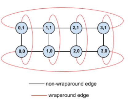
For clarity, the graph shows connections as undirected edges. In practice, each edge is a bidirectional connection between TPUs. The edges between one side of this grid and the opposite side are wrap-around edges.
Twisting this topology creates a symmetric 4×2 twisted torus topology:
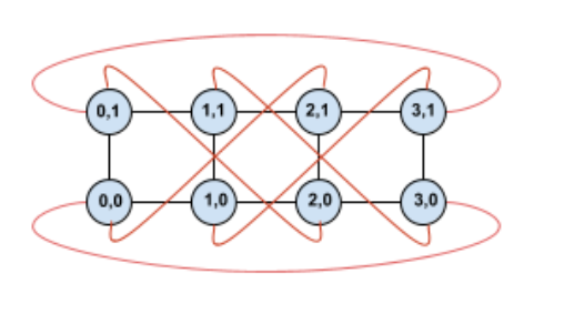
The difference between this twisted diagram and the untwisted one lies in the Y wrap-around edges. Instead of connecting to another TPU with the same X coordinate, these wrap-around edges shift to connect to the TPU at coordinate X+2 mod 4.
This principle applies to different dimension sizes and numbers of dimensions. The resulting network is symmetric if each dimension is equal to or twice the size of the smallest dimension.
The following table shows some of the supported twisted topologies and the theoretical increase in bisection bandwidth they provide versus untwisted topologies.
| Topology | Theoretical increase in bisection bandwidth versus a non-twisted torus |
|---|---|
| 4×4×8 | ~70% |
| 8x8x16 | |
| 12×12×24 | |
| 4×8×8 | ~40% |
| 8×16×16 |
Cloud TPU ICI resiliency
ICI resiliency helps improve fault tolerance of optical links and optical circuit switches (OCS) that connect TPUs between cubes. (ICI connections within a cube use copper links that are not impacted). ICI resiliency allows ICI connections to be routed around OCS and optical ICI faults. As a result, it improves the scheduling availability of TPU slices, with the trade-off of temporary degradation in ICI performance.
Similar to Cloud TPU v4, ICI resiliency is enabled by default for v5p slices that are one cube or larger (4x4x4 topology).
VM, host and slice properties
| Property | Value in a TPU |
|---|---|
| # of v5p chips | 4 |
| # of vCPUs | 208 (only half is usable if using NUMA binding to avoid cross-NUMA performance penalty) |
| RAM (GB) | 448 (only half is usable if using NUMA binding to avoid cross-NUMA performance penalty) |
| # of NUMA nodes | 2 |
| NIC throughput (Gbps) | 200 |
| Cores | Chips | Hosts/VMs | Cubes | |
|---|---|---|---|---|
| Host | 8 | 4 | 1 | |
| Cube (rack) | 128 | 64 | 16 | 1 |
| Largest supported slice | 12288 | 6144 | 1536 | 96 |
| v5p full Pod | 17920 | 8960 | 2240 | 140 |