
TPU v4
This document describes the architecture and supported configurations of Cloud TPU v4.
System architecture
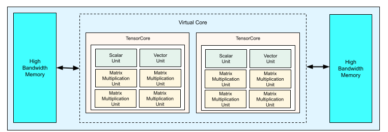
Each TPU v4 chip contains two TensorCores. Each TensorCore has four matrix-multiply units (MXUs), a vector unit, and a scalar unit. The following table shows the key specifications for a v4 TPU Pod.
| Specification | Values |
|---|---|
| Peak compute per chip | 275 teraflops (bf16 or int8) |
| HBM2 capacity and bandwidth | 32 GiB, 1200 GBps |
| Measured min/mean/max power | 90/170/192 W |
| TPU Pod size | 4096 chips |
| Interconnect topology | 3D mesh |
| Peak compute per Pod | 1.1 exaflops (bf16 or int8) |
| All-reduce bandwidth per Pod | 1.1 PB/s |
| Bisection bandwidth per Pod | 24 TB/s |
The following diagram illustrates a TPU v4 chip.
For more information about architectural details and performance characteristics for TPU v4, see TPU v4: An Optically Reconfigurable Supercomputer for Machine Learning with Hardware Support for Embeddings.
3D mesh and 3D torus
v4 TPUs have a direct connection to the nearest neighboring chips in 3 dimensions, resulting in a 3D mesh of networking connections. The connections can be configured as a 3D torus on slices where the topology, AxBxC, is either 2A=B=C or 2A=2B=C, where each dimension is a multiple of 4. For example, 4x4x8, 4x8x8, or 12x12x24. In general, the performance of a 3D torus configuration will be better than a 3D mesh configuration. For more information, see Twisted torus topologies.
Performance benefits of TPU v4 over v3
This section shows a memory-efficient way to run a sample training script on TPU v4, as well as the performance improvements for TPU v4 compared to TPU v3.
Memory system
Non Uniform Memory Access (NUMA) is a computer memory architecture for machines that have multiple CPUs. Each CPU has direct access to a block of high-speed memory. A CPU and its memory is called a NUMA node. NUMA nodes are connected to other NUMA nodes that are directly adjacent to each other. A CPU from one NUMA node can access memory in another NUMA node, but this access is slower than accessing memory within a NUMA node.
Software running on a multi-CPU machine can place data needed by a CPU within its NUMA node, increasing memory throughput. For more information about NUMA, see Non Uniform Memory Access on Wikipedia.
You can take advantage of NUMA-locality benefits by binding your training script to NUMA Node 0.
To enable NUMA node binding:
Install the numactl command line tool. numactl lets you run processes with a specific NUMA scheduling or memory placement policy.
 $ sudo apt-get update
 $ sudo apt-get install numactl
Bind your script code to NUMA Node 0. Replace your-training-script with the path to your training script.
$ numactl --cpunodebind=0 python3 your-training-script
Enable NUMA node binding if:
- If your workload has a heavy dependence on CPU workloads (for example, image classification, recommendation workloads) regardless of framework.
- If you are using a TPU runtime version without a -pod suffix (for example,
tpu-vm-tf-2.10.0-v4).
Other memory system differences:
- v4 TPU chips have a unified 32-GiB HBM memory space across the entire chip, enabling better coordination between the two on-chip TensorCores.
- Improved HBM performance using latest memory standards and speeds.
- Improved DMA performance profile with built-in support for high-performance striding at 512B granularities.
TensorCores
- Twice the number of MXUs and a higher clock rate delivering 275 max TFLOPS.
- 2x transposition and permutation bandwidth.
- Load-store memory access model for Common Memory (Cmem).
- Faster MXU weight loading bandwidth and 8-bit mode support to allow lower batch sizes and improved inference latency.
Inter-chip interconnect
Six interconnect links per chip to enable network topologies that have smaller network diameters.
Other
- x16 PCIE gen3 interface to host (direct connect).
- Improved security model.
- Improved energy efficiency.
Configurations
A TPU v4 Pod is composed of 4096 chips interconnected with reconfigurable high-speed links. TPU v4's flexible networking lets you connect the chips in a same-sized slice in multiple ways. When you create a TPU slice, you specify the TPU version and the number of TPU resources you require.
You specify a TPU topology using a 3-tuple, AxBxC where A<=B<=C and A, B, C are either all <= 4 or are all integer multiples of 4. The values A, B, and C are the chip counts in each of the three dimensions.
Topologies where 2A=B=C or 2A=2B=C also have topology variants optimized for all-to-all communication, for example, 4×4×8, 8×8×16, and 12×12×24. These are known as twisted torus topologies.
The following illustrations show some common TPU v4 topologies.
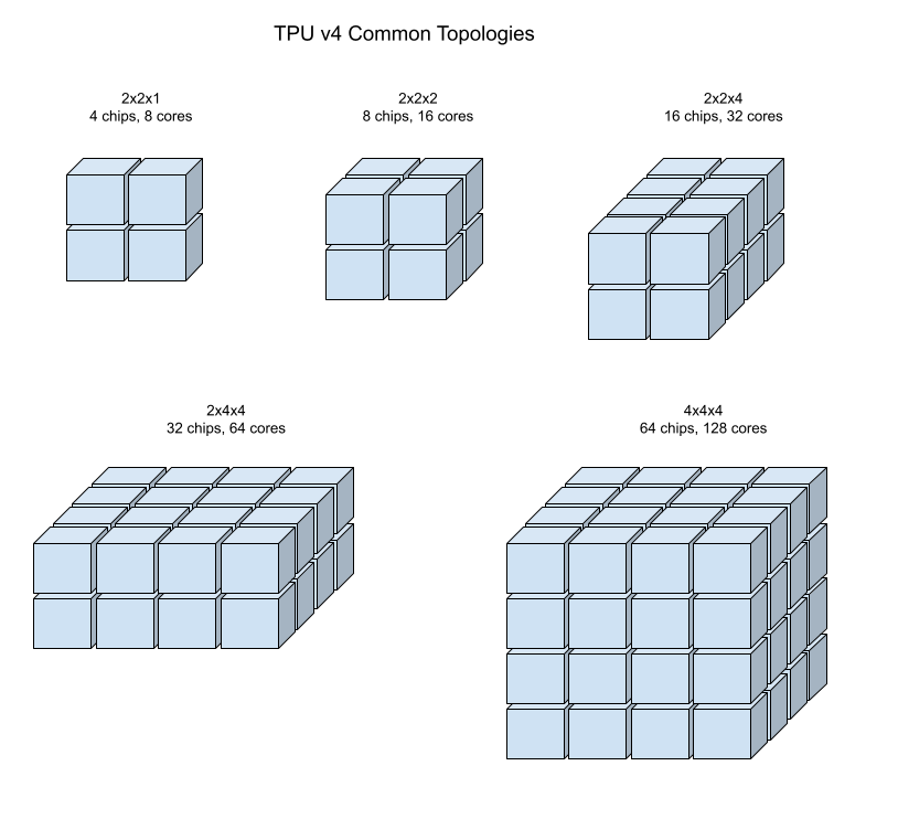
Larger slices can be built from one or more 4x4x4 "cubes" of chips.
For more information about managing TPUs, see Manage TPUs. For more information about the system architecture of Cloud TPU, see System architecture.
Twisted torus topologies
For some 3D slice shapes, you can use a twisted torus topology. These topologies offer significantly higher bisection bandwidth. For example, a 4x4x8 twisted topology provides a 70% theoretical increase in bisection bandwidth compared to a non-twisted 4x4x8 slice. This increased bandwidth helps workloads that use global communication patterns. Twisted topologies can improve performance for most models, with large TPU embedding workloads providing the greatest benefit. TPU software supports twisted topologies on slices where each dimension is either equal to or twice the size of the smallest dimension. For example, 4x4x8, 4×8×8, or 12x12x24. Twisted topologies are supported on TPU v4 and TPU v5p through the Cloud TPU API.
For workloads that use data parallelism as the only parallelism strategy, twisted topologies might perform slightly better. With large language models (LLMs), twisted topology performance varies depending on the type of parallelism used (for example, data parallelism or model parallelism). To find the best performance for your model, train your LLM both with and without a twisted topology. Some experiments on the FSDP MaxText model showed 1-2 percentage point improvements in model FLOPs utilization (MFU) when using a twisted topology.
The main benefit of twisted topologies is that they change an asymmetric torus topology (for example, 4×4×8) into a symmetric one. A symmetric topology offers:
- Improved load balancing
- Higher bisection bandwidth
- Shorter packet routes
These benefits result in improved performance for many global communication patterns.
For example, consider this 4×2 torus topology with TPUs labeled with X and Y coordinates in the slice:
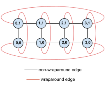
For clarity, the graph shows connections as undirected edges. In practice, each edge is a bidirectional connection between TPUs. The edges between one side of this grid and the opposite side are wrap-around edges.
Twisting this topology creates a symmetric 4×2 twisted torus topology:
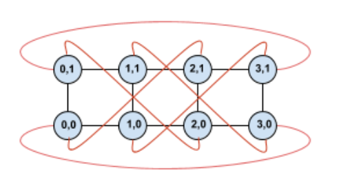
The difference between this twisted diagram and the untwisted one lies in the Y wrap-around edges. Instead of connecting to another TPU with the same X coordinate, these wrap-around edges shift to connect to the TPU at coordinate X+2 mod 4.
This principle applies to different dimension sizes and numbers of dimensions. The resulting network is symmetric if each dimension is equal to or twice the size of the smallest dimension.
The following table shows some of the supported twisted topologies and the theoretical increase in bisection bandwidth they provide versus untwisted topologies.
| Topology | Theoretical increase in bisection bandwidth versus a non-twisted torus |
|---|---|
| 4×4×8 | ~70% |
| 8x8x16 | |
| 12×12×24 | |
| 4×8×8 | ~40% |
| 8×16×16 |
TPU v4 topology variants
Some topologies containing the same number of chips can be arranged in different ways. For example, a TPU slice with 512 chips (1024 TensorCores) can be configured using the following topologies: 4x4x32, 4x8x16, or 8x8x8. A TPU slice with 2048 chips (4096 TensorCores) offers even more topology options: 4x4x128, 4x8x64, 4x16x32, and 8x16x16.
The default topology associated with a given chip count is the one that's most similar to a cube. This shape is likely the best choice for data-parallel ML training. Other topologies can be useful for workloads with multiple kinds of parallelism (for example, model and data parallelism, or spatial partitioning of a simulation). These workloads perform best if the topology is matched to the parallelism used. For example, placing 4-way model parallelism on the X dimension and 256-way data parallelism on the Y and Z dimensions matches a 4x16x16 topology.
Models with multiple dimensions of parallelism perform best with their parallelism dimensions mapped to TPU topology dimensions. These are usually data and model parallel large language models (LLMs). For example, for a TPU v4 slice with topology 8x16x16, the TPU topology dimensions are 8, 16 and 16. It is more performant to use 8-way or 16-way model parallelism (mapped to one of the physical TPU topology dimensions). A 4-way model parallelism would be sub-optimal with this topology, since it's not aligned with any of the TPU topology dimensions, but it would be optimal with a 4x16x32 topology on the same number of chips.
TPU v4 configurations consist of two groups, those with topologies smaller than 64 chips (small topologies) and those with topologies greater than 64 chips (large topologies).
Small v4 topologies
Cloud TPU supports the following TPU v4 slices smaller than 64 chips, a 4x4x4 cube. You can create these small v4 topologies using either their TensorCore-based name (for example, v4-32), or their topology (for example, 2x2x4):
| Name (based on TensorCore count) | Number of chips | Topology |
| v4-8 | 4 | 2x2x1 |
| v4-16 | 8 | 2x2x2 |
| v4-32 | 16 | 2x2x4 |
| v4-64 | 32 | 2x4x4 |
Large v4 topologies
TPU v4 slices are available in increments of 64 chips, with shapes that are
multiples of 4 on all three dimensions. The dimensions must be in
increasing order. Several examples are shown in the following table. A few of
these topologies are "custom" topologies that can only be created using the
--type and --topology flags because there is more than one way to arrange
the chips.
| Name (based on TensorCore count) | Number of chips | Topology |
| v4-128 | 64 | 4x4x4 |
| v4-256 | 128 | 4x4x8 |
| v4-512 | 256 | 4x8x8 |
custom topology: must use the --type and --topology flags |
256 | 4x4x16 |
| v4-1024 | 512 | 8x8x8 |
| v4-1536 | 768 | 8x8x12 |
| v4-2048 | 1024 | 8x8x16 |
custom topology: must use --type and --topology flags |
1024 | 4x16x16 |
| v4-4096 | 2048 | 8x16x16 |
| … | … | … |