
This page describes how to verify the network cabling for Google Distributed Cloud (GDC) air-gapped appliance, and connect the bootstrapper device.
Refer to the following images while following the instructions.
Figure 1. The TOR switch, with labelled ports.
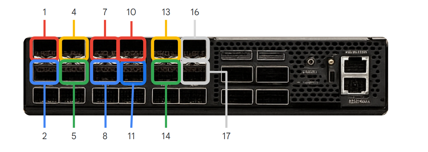
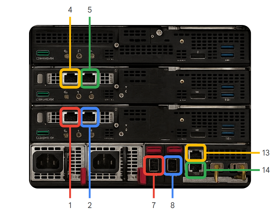
Figure 2. The chassis and bare metal nodes, with labelled ports.
Verify the cabling
- Verify that port labeled "1" on the TOR switch (Figure 1) is connected to the port labeled "1" in the Chassis and Nodes (Figure 2).
- Continue the process for the ports 2, 4, 5, 7, 8, 13, and 14 on the TOR switch (Figure 1), verifying that each is connected to the corresponding numbered port on the chassis or nodes (Figure 2).
Connect port 16 and 17 of the TOR switch to your network.
ToR Switch Port (xx-aa-tesw01) Connected Device Device Port Notes eth1/1Server 1 (bm01) s1p1Data eth1/2Server 1 (bm01) s1p2Data eth1/4Server 2 (bm02) s1p1Data eth1/5Server 2 (bm02) s1p2Data eth1/7Server 3 (bm03) s1p1Data eth1/8Server 3 (bm03) s1p2Data eth1/13Chassis (chs01) iLOManagement (HPE iLO) eth1/14Chassis (chs01) LOM1Management (LAN on Motherboard) Explanation of terms:
- tesw01: Top of Rack switch.
- ethx/xx: Port number on the switch.
- bm0x: Bare metal server (e.g., bm01 is Server 1).
- s1p1, s1p2: Network ports on the servers.
- chs01: Chassis.
- iLO: HPE Integrated Lights-Out port for out-of-band management.
- LOM1: LAN on motherboard port on the chassis.
Figure 3. The connections between the ports.

Verify that link lights show green for all of the ports you have verified in the previous steps.
If the link lights remain yellow or red, try again with different cables or hardware before opening a support case.