# Running distributed services on GKE private clusters using Cloud Service Mesh
This document shows you how to run distributed services on multiple
Google Kubernetes Engine (GKE) clusters in Google Cloud using Cloud Service Mesh.
This document also shows you how to expose a distributed service using
Multi Cluster Ingress and Cloud Service Mesh. You can use this document to configure
non-private GKE clusters; the document highlights the
configuration that is intended strictly for private clusters.
This document is for platform administrators and service operators who have
basic knowledge of Kubernetes. Some knowledge of service mesh is beneficial,
although not required. Cloud Service Mesh is based on the open source Istio
technology. For more information about service mesh and Istio, see
[istio.io](https://istio.io/).
A distributed service is a Kubernetes Service that acts as a single logical
service. Distributed services are more resilient than Kubernetes services
because they run on multiple Kubernetes clusters in the same namespace. A
distributed service remains up even if one or more GKE
clusters are down, as long as the healthy clusters are able to serve the desired
load.
Kubernetes Services are known only to the Kubernetes API server of the cluster
they run on. If the Kubernetes cluster is down (for example during a scheduled
maintenance), all Kubernetes Services running on that cluster are also down.
Running distributed services makes cluster lifecycle management easier because
you can bring clusters down for maintenance or upgrades while other clusters
service traffic. In order to create a distributed service, service mesh
functionality provided by Cloud Service Mesh is used to link services running
on multiple clusters together to act as a single logical service.
GKE private clusters let you configure the nodes and API
server as private resources available only on the Virtual Private Cloud (VPC)
network. Running distributed services in GKE private
clusters gives enterprises both secure and reliable services.
## Architecture
This tutorial uses the architecture shown in the following diagram:
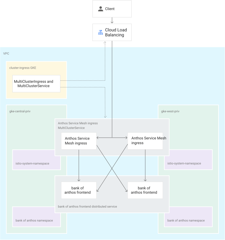
In the preceding diagram, the architecture includes the following clusters:
- Two clusters (`gke-central-priv` and `gke-west-priv`) act as identical GKE private clusters in two different regions.
- A separate cluster (`ingress-config`) acts as the control plane cluster that configures Multi Cluster Ingress.
In this tutorial, you deploy the
[Bank of Anthos](https://github.com/GoogleCloudPlatform/bank-of-anthos)
sample application on two GKE private clusters
(`gke-central-priv` and `gke-west-priv`). Bank of Anthos is a sample
microservices application that consists of multiple microservices and SQL
databases that simulate an online banking app. The application consists of a web
frontend that clients can access, and several backend services such as balance,
ledger, and account services that simulate a bank.
The application includes two PostgreSQL databases that are installed in
Kubernetes as StatefulSets. One database is used for transactions, while the
other database is used for user accounts. All services except the two databases
run as distributed services. This means that Pods for all services run in both
application clusters (in the same namespace), and Cloud Service Mesh is
configured so that each service appears as a single logical service.
## Objectives
- Create three GKE clusters.
- Configure two of the GKE clusters as private clusters (`gke-central-priv` and `gke-west-priv`).
- Configure one GKE cluster (`ingress-config`) as the central configuration cluster. This cluster acts as a config cluster for Multi Cluster Ingress.
- Configure networking (NAT Gateways, Cloud Router, and firewall rules) to allow inter-cluster and egress traffic from the two private GKE clusters.
- Configure authorized networks to allow API service access from Cloud Shell to the two private GKE clusters.
- Deploy and configure multi-cluster Cloud Service Mesh to the two private clusters in multi-primary mode. Multi-primary mode deploys an Cloud Service Mesh control plane in both clusters.
- Deploy the Bank of Anthos application on the two private clusters. All services except the databases are deployed as distributed services (Pods running on both private clusters).
- Monitor services using Cloud Service Mesh.
- Configure Multi Cluster Ingress on the Bank of Anthos `frontend` services. This allows external clients (for example, your web browser) to access a distributed service running on a fleet of private GKE clusters.
## Costs
In this document, you use the following billable components of Google Cloud:
- [GKE](https://docs.cloud.google.com/kubernetes-engine/pricing)
- [Virtual Private Cloud networks](https://docs.cloud.google.com/vpc/network-pricing#vpc-pricing)
- [Virtual Private Cloud load balancing](https://docs.cloud.google.com/vpc/network-pricing#lb)
To generate a cost estimate based on your projected usage,
use the [pricing calculator](https://docs.cloud.google.com/products/calculator).
New Google Cloud users might be eligible for a [free trial](https://docs.cloud.google.com/free).
## Before you begin
1. In the Google Cloud console, on the project selector page,
select or create a Google Cloud project.
**Roles required to select or create a project**
- **Select a project**: Selecting a project doesn't require a specific IAM role---you can select any project that you've been granted a role on.
- **Create a project** : To create a project, you need the Project Creator role (`roles/resourcemanager.projectCreator`), which contains the `resourcemanager.projects.create` permission. [Learn how to grant
roles](https://docs.cloud.google.com/iam/docs/granting-changing-revoking-access).
> [!NOTE]
> **Note**: If you don't plan to keep the resources that you create in this procedure, create a project instead of selecting an existing project. After you finish these steps, you can delete the project, removing all resources associated with the project.
[Go to project selector](https://console.cloud.google.com/projectselector2/home/dashboard)
2.
[Verify that billing is enabled for your Google Cloud project](https://docs.cloud.google.com/billing/docs/how-to/verify-billing-enabled.md.txt#confirm_billing_is_enabled_on_a_project).
3.
In the Google Cloud console, activate Cloud Shell.
[Activate Cloud Shell](https://console.cloud.google.com/?cloudshell=true)
At the bottom of the Google Cloud console, a
[Cloud Shell](https://docs.cloud.google.com/shell/docs/how-cloud-shell-works.md.txt)
session starts and displays a command-line prompt. Cloud Shell is a shell environment
with the Google Cloud CLI
already installed and with values already set for
your current project. It can take a few seconds for the session to initialize.
You run all commands in this tutorial from Cloud Shell.
4. Define environment variables that are used throughout this tutorial.
The variables define cluster names, regions, zones, IP addressing, and
Cloud Service Mesh versions that are used in this tutorial.
1. Replace `YOUR_PROJECT_ID` with your project ID:
```bash
export PROJECT_ID=YOUR_PROJECT_ID
gcloud config set project ${PROJECT_ID}
```
2. Set the remaining environment variables:
```bash
export CLUSTER_1=gke-west-priv
export CLUSTER_2=gke-central-priv
export CLUSTER_1_ZONE=us-west2-a
export CLUSTER_1_REGION=us-west2
export CLUSTER_1_MASTER_IPV4_CIDR=172.16.0.0/28
export CLUSTER_2_ZONE=us-central1-a
export CLUSTER_2_REGION=us-central1
export CLUSTER_2_MASTER_IPV4_CIDR=172.16.1.0/28
export CLUSTER_INGRESS=gke-ingress
export CLUSTER_INGRESS_ZONE=us-west1-a
export CLUSTER_INGRESS_REGION=us-west1
export CLUSTER_INGRESS_MASTER_IPV4_CIDR=172.16.2.0/28
export WORKLOAD_POOL=${PROJECT_ID}.svc.id.goog
export ASM_VERSION=1.10
export CLOUDSHELL_IP=$(dig +short myip.opendns.com @resolver1.opendns.com)
```
## Prepare your environment
1. In Cloud Shell, enable the APIs:
```bash
gcloud services enable \
--project=${PROJECT_ID} \
container.googleapis.com \
mesh.googleapis.com \
gkehub.googleapis.com
```
2. Enable the Cloud Service Mesh Fleet for your project:
```bash
gcloud container fleet mesh enable --project=${PROJECT_ID}
```
## Prepare networking for private GKE clusters
In this section, you prepare networking for the private
GKE clusters that you use to run distributed services.
Private GKE cluster nodes aren't assigned a public IP
address. All nodes in a private GKE cluster are assigned a
private VPC IP address (in the RFC 1918 address space). This means that Pods
that need to access external resources (outside the VPC network) require a
[Cloud NAT gateway](https://docs.cloud.google.com/nat/docs/overview.md.txt).
Cloud NAT gateways are regional NAT gateways that allow Pods with internal IP
addresses to communicate to the internet. In this tutorial, you configure a
Cloud NAT gateway in each of two regions. Multiple clusters within a region
can use the same NAT gateway.
1. In Cloud Shell, create and reserve two external IP addresses for
the two NAT gateways:
```bash
gcloud compute addresses create ${CLUSTER_1_REGION}-nat-ip \
--project=${PROJECT_ID} \
--region=${CLUSTER_1_REGION}
gcloud compute addresses create ${CLUSTER_2_REGION}-nat-ip \
--project=${PROJECT_ID} \
--region=${CLUSTER_2_REGION}
```
2. Store the IP address and name of the IP addresses in variables:
```bash
export NAT_REGION_1_IP_ADDR=$(gcloud compute addresses describe ${CLUSTER_1_REGION}-nat-ip \
--project=${PROJECT_ID} \
--region=${CLUSTER_1_REGION} \
--format='value(address)')
export NAT_REGION_1_IP_NAME=$(gcloud compute addresses describe ${CLUSTER_1_REGION}-nat-ip \
--project=${PROJECT_ID} \
--region=${CLUSTER_1_REGION} \
--format='value(name)')
export NAT_REGION_2_IP_ADDR=$(gcloud compute addresses describe ${CLUSTER_2_REGION}-nat-ip \
--project=${PROJECT_ID} \
--region=${CLUSTER_2_REGION} \
--format='value(address)')
export NAT_REGION_2_IP_NAME=$(gcloud compute addresses describe ${CLUSTER_2_REGION}-nat-ip \
--project=${PROJECT_ID} \
--region=${CLUSTER_2_REGION} \
--format='value(name)')
```
3. Create Cloud NAT gateways in the two regions of the private
GKE clusters:
```bash
gcloud compute routers create rtr-${CLUSTER_1_REGION} \
--network=default \
--region ${CLUSTER_1_REGION}
gcloud compute routers nats create nat-gw-${CLUSTER_1_REGION} \
--router=rtr-${CLUSTER_1_REGION} \
--region ${CLUSTER_1_REGION} \
--nat-external-ip-pool=${NAT_REGION_1_IP_NAME} \
--nat-all-subnet-ip-ranges \
--enable-logging
gcloud compute routers create rtr-${CLUSTER_2_REGION} \
--network=default \
--region ${CLUSTER_2_REGION}
gcloud compute routers nats create nat-gw-${CLUSTER_2_REGION} \
--router=rtr-${CLUSTER_2_REGION} \
--region ${CLUSTER_2_REGION} \
--nat-external-ip-pool=${NAT_REGION_2_IP_NAME} \
--nat-all-subnet-ip-ranges \
--enable-logging
```
4. Create a firewall rule that allows Pod-to-Pod communication and Pod-to-API
server communication. Pod-to-Pod communication lets the distributed
services communicate with each other across GKE
clusters. Pod-to-API server communication lets the Cloud Service Mesh
control plane query GKE clusters for service discovery.
```bash
gcloud compute firewall-rules create all-pods-and-master-ipv4-cidrs \
--project ${PROJECT_ID} \
--network default \
--allow all \
--direction INGRESS \
--source-ranges 10.0.0.0/8,${CLUSTER_1_MASTER_IPV4_CIDR},${CLUSTER_2_MASTER_IPV4_CIDR},${CLUSTER_INGRESS_MASTER_IPV4_CIDR}
```
The networking is now prepared. In this tutorial, you use the entire
`10.0.0.0/8` IP address range, which includes all Pod ranges. We recommend that
you create a stricter firewall rule in production, based on your conditions and
requirements.
## Create private GKE clusters
In this section, you create the two private GKE clusters
where the sample app is deployed. In this tutorial, the private
GKE cluster nodes have private IP addresses, and the API
server has a public endpoint. However, access to the API server is restricted
using authorized networks.
1. In Cloud Shell, create two private clusters that have authorized
networks. Configure the clusters to allow access from the Pod IP CIDR range
(for the Cloud Service Mesh control plane) and from Cloud Shell
so that you can access the clusters from your terminal.
```bash
gcloud container clusters create ${CLUSTER_1} \
--project ${PROJECT_ID} \
--zone=${CLUSTER_1_ZONE} \
--machine-type "e2-standard-4" \
--num-nodes "3" --min-nodes "3" --max-nodes "5" \
--enable-ip-alias --enable-autoscaling \
--workload-pool=${WORKLOAD_POOL} \
--enable-private-nodes \
--master-ipv4-cidr=${CLUSTER_1_MASTER_IPV4_CIDR} \
--enable-master-authorized-networks \
--master-authorized-networks $NAT_REGION_1_IP_ADDR/32,$NAT_REGION_2_IP_ADDR/32,$CLOUDSHELL_IP/32
gcloud container clusters create ${CLUSTER_2} \
--project ${PROJECT_ID} \
--zone=${CLUSTER_2_ZONE} \
--machine-type "e2-standard-4" \
--num-nodes "3" --min-nodes "3" --max-nodes "5" \
--enable-ip-alias --enable-autoscaling \
--workload-pool=${WORKLOAD_POOL} \
--enable-private-nodes \
--master-ipv4-cidr=${CLUSTER_2_MASTER_IPV4_CIDR} \
--enable-master-authorized-networks \
--master-authorized-networks $NAT_REGION_1_IP_ADDR/32,$NAT_REGION_2_IP_ADDR/32,$CLOUDSHELL_IP/32
```
The authorized networks contain the public IP addresses on the
Cloud NAT gateways. Because the API server endpoint for a private
cluster is a public endpoint, Pods that run in a private cluster must use a
Cloud NAT gateway to access the public API server endpoints.
The Cloud Shell IP address is also part of the authorized
networks, which lets you access and manage clusters from your
Cloud Shell terminal. Cloud Shell public-facing IP
addresses are dynamic, so every time you start Cloud Shell, you
might get a different public IP address. When you get a new IP address, you
lose access to the clusters because the new IP address isn't part of the
authorized networks for the two clusters.
If you lose access to the clusters, update the clusters' authorized
networks to include the new Cloud Shell IP address:
1. Get the updated Cloud Shell public IP address:
```bash
export CLOUDSHELL_IP=$(dig +short myip.opendns.com @resolver1.opendns.com)
```
2. Update the authorized networks for the two clusters:
```bash
gcloud container clusters update ${CLUSTER_1} \
--zone=${CLUSTER_1_ZONE} \
--enable-master-authorized-networks \
--master-authorized-networks $NAT_REGION_1_IP_ADDR/32,$NAT_REGION_2_IP_ADDR/32,$CLOUDSHELL_IP/32
gcloud container clusters update ${CLUSTER_2} \
--zone=${CLUSTER_2_ZONE} \
--enable-master-authorized-networks \
--master-authorized-networks $NAT_REGION_1_IP_ADDR/32,$NAT_REGION_2_IP_ADDR/32,$CLOUDSHELL_IP/32
```
2. Verify that all clusters are running:
```bash
gcloud container clusters list
```
The output looks like the following:
NAME LOCATION MASTER_VERSION MASTER_IP MACHINE_TYPE NODE_VERSION NUM_NODES STATUS
gke-central-priv us-central1-a 1.16.15-gke.6000 35.238.99.104 e2-standard-4 1.16.15-gke.6000 3 RUNNING
gke-west-priv us-west2-a 1.16.15-gke.6000 34.94.188.180 e2-standard-4 1.16.15-gke.6000 3 RUNNING
3. Connect to both clusters to generate entries in the kubeconfig file:
```bash
touch ~/asm-kubeconfig && export KUBECONFIG=~/asm-kubeconfig
gcloud container clusters get-credentials ${CLUSTER_1} --zone ${CLUSTER_1_ZONE}
gcloud container clusters get-credentials ${CLUSTER_2} --zone ${CLUSTER_2_ZONE}
```
You use the kubeconfig file to authenticate to clusters by creating a user
and context for each cluster. After you generate entries in the kubeconfig
file, you can quickly switch context between clusters.
4. Rename the cluster contexts for convenience:
```bash
kubectl config rename-context \
gke_${PROJECT_ID}_${CLUSTER_1_ZONE}_${CLUSTER_1} ${CLUSTER_1}
kubectl config rename-context \
gke_${PROJECT_ID}_${CLUSTER_2_ZONE}_${CLUSTER_2} ${CLUSTER_2}
```
5. Confirm that both cluster contexts are properly renamed and configured:
```bash
kubectl config get-contexts --output="name"
```
The output looks like the following:
gke-central-priv
gke-west-priv
6. Register your clusters to a fleet:
```bash
gcloud container fleet memberships register ${CLUSTER_1} --gke-cluster=${CLUSTER_1_ZONE}/${CLUSTER_1} --enable-workload-identity
gcloud container fleet memberships register ${CLUSTER_2} --gke-cluster=${CLUSTER_2_ZONE}/${CLUSTER_2} --enable-workload-identity
```
You have now created and renamed your private GKE
clusters.
## Install Cloud Service Mesh
In this section, you install Cloud Service Mesh on the two
GKE clusters and configure the clusters for cross-cluster
service discovery.
1. In Cloud Shell, install Cloud Service Mesh on both clusters using the `fleet API`:
```bash
gcloud container fleet mesh update --management automatic --memberships ${CLUSTER_1},${CLUSTER_2}
```
> [!NOTE]
> **Note:** This process should be complete within 10 minutes.
2. After the managed Cloud Service Mesh is enabled on the clusters, set a watch for the mesh to be installed:
```bash
watch -g "gcloud container fleet mesh describe | grep 'code: REVISION_READY'"
```
3. Install Cloud Service Mesh ingress gateways
for both clusters:
```bash
kubectl --context=${CLUSTER_1} create namespace asm-ingress
kubectl --context=${CLUSTER_1} label namespace asm-ingress istio-injection=enabled --overwrite
kubectl --context=${CLUSTER_2} create namespace asm-ingress
kubectl --context=${CLUSTER_2} label namespace asm-ingress istio-injection=enabled --overwrite
cat <<'EOF' > asm-ingress.yaml
apiVersion: v1
kind: Service
metadata:
name: asm-ingressgateway
namespace: asm-ingress
spec:
type: LoadBalancer
selector:
asm: ingressgateway
ports:
- port: 80
name: http
- port: 443
name: https
---
apiVersion: apps/v1
kind: Deployment
metadata:
name: asm-ingressgateway
namespace: asm-ingress
spec:
selector:
matchLabels:
asm: ingressgateway
template:
metadata:
annotations:
# This is required to tell Anthos Service Mesh to inject the gateway with the
# required configuration.
inject.istio.io/templates: gateway
labels:
asm: ingressgateway
spec:
containers:
- name: istio-proxy
image: auto # The image will automatically update each time the pod starts.
---
apiVersion: rbac.authorization.k8s.io/v1
kind: Role
metadata:
name: asm-ingressgateway-sds
namespace: asm-ingress
rules:
- apiGroups: [""]
resources: ["secrets"]
verbs: ["get", "watch", "list"]
---
apiVersion: rbac.authorization.k8s.io/v1
kind: RoleBinding
metadata:
name: asm-ingressgateway-sds
namespace: asm-ingress
roleRef:
apiGroup: rbac.authorization.k8s.io
kind: Role
name: asm-ingressgateway-sds
subjects:
- kind: ServiceAccount
name: default
EOF
kubectl --context=${CLUSTER_1} apply -f asm-ingress.yaml
kubectl --context=${CLUSTER_2} apply -f asm-ingress.yaml
```
4. Verify that the Cloud Service Mesh ingress gateways are deployed:
```bash
kubectl --context=${CLUSTER_1} get pod,service -n asm-ingress
kubectl --context=${CLUSTER_2} get pod,service -n asm-ingress
```
The output for both clusters looks like the following:
NAME READY STATUS RESTARTS AGE
pod/asm-ingressgateway-5894744dbd-zxlgc 1/1 Running 0 84s
NAME TYPE CLUSTER-IP EXTERNAL-IP PORT(S) AGE
service/asm-ingressgateway LoadBalancer 10.16.2.131 34.102.100.138 80:30432/TCP,443:30537/TCP 92s
After the Cloud Service Mesh control plane and ingress gateways are installed for both clusters,
cross-cluster service discovery is enabled with the fleet API. Cross-cluster service
discovery lets the two clusters discover service endpoints from the remote
cluster. Distributed services run on multiple clusters in the
[same namespace](https://docs.cloud.google.com/anthos/multicluster-management/fleets#namespace_sameness).
For both Cloud Service Mesh control planes to discover all endpoints of
a distributed service, Cloud Service Mesh must have access to all clusters
that are running the distributed service. This example uses two clusters,
so both clusters must be able to query the remote cluster for service
endpoints. With managed Cloud Service Mesh enabled with the fleet API, endpoint discovery is automatically configured.
The clusters and Cloud Service Mesh are now configured.
## Deploy the Bank of Anthos application
1. In Cloud Shell, clone the Bank of Anthos GitHub repository:
```bash
git clone https://github.com/GoogleCloudPlatform/bank-of-anthos.git ${HOME}/bank-of-anthos
```
2. Create and label a `bank-of-anthos` namespace in both clusters. The
label allows automatic injection of the sidecar Envoy proxies in every Pod
within the labeled namespace.
```bash
# cluster_1
kubectl create --context=${CLUSTER_1} namespace bank-of-anthos
kubectl label --context=${CLUSTER_1} namespace bank-of-anthos istio-injection=enabled
# cluster_2
kubectl create --context=${CLUSTER_2} namespace bank-of-anthos
kubectl label --context=${CLUSTER_2} namespace bank-of-anthos istio-injection=enabled
```
3. Deploy the Bank of Anthos application to both clusters in the
`bank-of-anthos` namespace.
```bash
# The following secret is used for user account creation and authentication
kubectl --context=$CLUSTER_1 -n bank-of-anthos apply -f ${HOME}/bank-of-anthos/extras/jwt/jwt-secret.yaml
kubectl --context=$CLUSTER_2 -n bank-of-anthos apply -f ${HOME}/bank-of-anthos/extras/jwt/jwt-secret.yaml
# Deploy all manifests to both clusters
kubectl --context=$CLUSTER_1 -n bank-of-anthos apply -f ${HOME}/bank-of-anthos/kubernetes-manifests
kubectl --context=$CLUSTER_2 -n bank-of-anthos apply -f ${HOME}/bank-of-anthos/kubernetes-manifests
```
The Kubernetes services need to be in both clusters for service
discovery. When a service in one of the clusters tries to make a request,
it first performs a DNS lookup for the hostname to get the IP address. In
GKE, the `kube-dns` server running in the cluster
handles this lookup, so a configured Service definition is required.
4. Delete the `StatefulSets` from one cluster so that the two PostgreSQL
databases exist in only one of the clusters:
```bash
# Delete the two DB statefulSets from Cluster2
kubectl --context=$CLUSTER_2 -n bank-of-anthos delete statefulset accounts-db
kubectl --context=$CLUSTER_2 -n bank-of-anthos delete statefulset ledger-db
```
5. Make sure that all Pods are running in both clusters:
1. Get Pods from `cluster_1`:
```bash
kubectl --context=${CLUSTER_1} -n bank-of-anthos get pod
```
The output looks like the following:
NAME READY STATUS RESTARTS AGE
accounts-db-0 2/2 Running 0 9m54s
balancereader-c5d664b4c-xmkrr 2/2 Running 0 9m54s
contacts-7fd8c5fb6-wg9xn 2/2 Running 1 9m53s
frontend-7b7fb9b665-m7cw7 2/2 Running 1 9m53s
ledger-db-0 2/2 Running 0 9m53s
ledgerwriter-7b5b6db66f-xhbp4 2/2 Running 0 9m53s
loadgenerator-7fb54d57f8-g5lz5 2/2 Running 0 9m52s
transactionhistory-7fdb998c5f-vqh5w 2/2 Running 1 9m52s
userservice-76996974f5-4wlpf 2/2 Running 1 9m52s
2. Get Pods from `cluster_2`:
```bash
kubectl --context=${CLUSTER_2} -n bank-of-anthos get pod
```
The output looks like the following:
NAME READY STATUS RESTARTS AGE
balancereader-c5d664b4c-bn2pl 2/2 Running 0 9m54s
contacts-7fd8c5fb6-kv8cp 2/2 Running 0 9m53s
frontend-7b7fb9b665-bdpp4 2/2 Running 0 9m53s
ledgerwriter-7b5b6db66f-297c2 2/2 Running 0 9m52s
loadgenerator-7fb54d57f8-tj44v 2/2 Running 0 9m52s
transactionhistory-7fdb998c5f-xvmtn 2/2 Running 0 9m52s
userservice-76996974f5-mg7t6 2/2 Running 0 9m51s
6. Deploy the Cloud Service Mesh configs to both clusters. This creates a
[Gateway](https://istio.io/latest/docs/reference/config/networking/gateway/)
in the `asm-ingress` namespace and
[VirtualService](https://istio.io/latest/docs/reference/config/networking/virtual-service/)
in the `bank-of-anthos` namespaces for the `frontend` service, which lets you ingress traffic to the `frontend`
service.
`Gateways` are generally owned by the platform admins or the network admins
team. Therefore, the `Gateway` resource is created in the Ingress Gateway
namespace owned by the platform admin and could be used in other namespaces
via their own `VirtualService` entries. This is a 'Shared Gateway' model.
```bash
cat <<'EOF' > asm-vs-gateway.yaml
apiVersion: networking.istio.io/v1alpha3
kind: Gateway
metadata:
name: asm-ingressgateway
namespace: asm-ingress
spec:
selector:
asm: ingressgateway
servers:
- port:
number: 80
name: http
protocol: HTTP
hosts:
- "*"
---
apiVersion: networking.istio.io/v1alpha3
kind: VirtualService
metadata:
name: frontend
namespace: bank-of-anthos
spec:
hosts:
- "*"
gateways:
- asm-ingress/asm-ingressgateway
http:
- route:
- destination:
host: frontend
port:
number: 80
EOF
kubectl --context=$CLUSTER_1 apply -f asm-vs-gateway.yaml
kubectl --context=$CLUSTER_2 apply -f asm-vs-gateway.yaml
```
You have now deployed the Bank of Anthos application on two private
GKE clusters. All services run as distributed services,
except for the database.
## Inspect distributed services
In this section, you use the `istioctl` tool to inspect the proxy-config of any
of the proxies. Doing this lets you see that the sidecar proxies see two Pods
for every service, with one Pod running in each cluster.
1. In Cloud Shell, , inspect the proxy-config Endpoints list on the
`frontend` Pod in `cluster_1`:
```bash
export FRONTEND1=$(kubectl get pod -n bank-of-anthos -l app=frontend \
--context=${CLUSTER_1} -o jsonpath='{.items[0].metadata.name}')
istioctl proxy-config endpoints \
--context $CLUSTER_1 -n bank-of-anthos $FRONTEND1 | grep bank-of-anthos
```
The output looks like the following:
10.12.0.6:5432 HEALTHY OK outbound|5432||accounts-db.bank-of-anthos.svc.cluster.local
10.12.0.7:8080 HEALTHY OK outbound|8080||balancereader.bank-of-anthos.svc.cluster.local
10.12.0.8:8080 HEALTHY OK outbound|8080||transactionhistory.bank-of-anthos.svc.cluster.local
10.12.0.9:8080 HEALTHY OK outbound|8080||userservice.bank-of-anthos.svc.cluster.local
10.12.1.10:8080 HEALTHY OK outbound|8080||ledgerwriter.bank-of-anthos.svc.cluster.local
10.12.1.9:8080 HEALTHY OK outbound|8080||contacts.bank-of-anthos.svc.cluster.local
10.12.2.11:5432 HEALTHY OK outbound|5432||ledger-db.bank-of-anthos.svc.cluster.local
10.12.2.13:8080 HEALTHY OK outbound|80||frontend.bank-of-anthos.svc.cluster.local
10.76.1.10:8080 HEALTHY OK outbound|8080||transactionhistory.bank-of-anthos.svc.cluster.local
10.76.1.8:8080 HEALTHY OK outbound|8080||balancereader.bank-of-anthos.svc.cluster.local
10.76.1.9:8080 HEALTHY OK outbound|80||frontend.bank-of-anthos.svc.cluster.local
10.76.2.10:8080 HEALTHY OK outbound|8080||userservice.bank-of-anthos.svc.cluster.local
10.76.2.8:8080 HEALTHY OK outbound|8080||contacts.bank-of-anthos.svc.cluster.local
10.76.2.9:8080 HEALTHY OK outbound|8080||ledgerwriter.bank-of-anthos.svc.cluster.local
In the preceding output, each distributed service has two Endpoint IP
addresses. These are the Pod IP addresses, one for each cluster.
## Access Bank of Anthos
To access the Bank of Anthos application, you can use the `asm-ingressgateway`
Service public IP address from either cluster.
1. Get `asm-ingressgateway` IP addresses from both clusters:
```bash
kubectl --context ${CLUSTER_1} \
--namespace asm-ingress get svc asm-ingressgateway -o jsonpath='{.status.loadBalancer}' | grep "ingress"
kubectl --context ${CLUSTER_2} \
--namespace asm-ingress get svc asm-ingressgateway -o jsonpath='{.status.loadBalancer}' | grep "ingress"
```
The output looks like the following.
{"ingress":[{"ip":"35.236.4.18"}]}
{"ingress":[{"ip":"34.68.94.81"}]}
Copy one of the IP addresses to use in the next step.
2. Open a new tab in a web browser and go to either IP address from the
preceding output. The Bank of Anthos frontend should be displayed, which
lets you log in, deposit funds to your account, and transfer funds to other
accounts. The application should be fully functional.
## Visualize distributed services
You can visualize distributed services in Cloud Service Mesh.
1. To view your services, go to the
[**Service Mesh**](https://console.cloud.google.com/kubernetes/services)
page in the Google Cloud console.
[Go to Service Mesh](https://console.cloud.google.com/kubernetes/services)
You can view services in **Table** view or in a **Topology** view. The default view
is the table view, which shows all of your distributed services running in a
tabular format. To change views, click the view that you want to display.
2. In the **Tables** view, click the **`frontend distributed service`**.
When you click an individual service, you see a detailed view of the
service along with connected services.
In the service details view, you can create SLOs and view a historical
timeline of the service by clicking **Show Timeline**.
3. To view golden signals, on the side panel, click **Metrics**.
4. In the **Requests per seconds** chart, click **Breakdown By** and then
select **Location**.
The results display the requests per second from both clusters in the two
regions. The distributed service is healthy and both endpoints are serving
traffic.
5. To view the topology of your service mesh, on the side panel, click
**Anthos Service Mesh** , and then click **Topology View**.
6. To view additional data, hold your mouse pointer over the `frontend`
service. This displays information like requests per second to and from the
frontend to other services.
7. To view more details, click **Expand** on the `frontend` service. A
Service and a Workload are displayed. You can further expand workload into
two Deployments, expand the deployments into ReplicaSets, and expand the
ReplicaSets into Pods. When you expand all elements, you can see the
distributed `frontend` service which is essentially a Service and two Pods.
## Configure Multi Cluster Ingress
In this section, you create a Multi Cluster Ingress that sends traffic to the Bank
of GKE Enterprise `frontend` services running in both clusters. You use
[Cloud Load Balancing](https://docs.cloud.google.com/load-balancing/docs/load-balancing-overview.md.txt)
to create a load balancer that uses the `asm-ingressgateway` Services in both
clusters as backends. An `ingress-config` cluster is used to orchestrate
Multi Cluster Ingress configuration.
To create the load balancer, you use a `MultiClusterIngress` and one or more
`MultiClusterServices`. `MultiClusterIngress` and `MultiClusterService` objects
are multi-cluster analogs for the existing Kubernetes Ingress and Service
resources that are used in the single cluster context.
1. Enable the required GKE Enterprise, GKE Fleet, and
Multi Cluster Ingress APIs:
```bash
gcloud services enable \
anthos.googleapis.com \
multiclusterservicediscovery.googleapis.com \
multiclusteringress.googleapis.com
```
2. Create the `ingress-config` cluster. You can use any cluster, but we
recommend that you create a separate cluster for this purpose.
```bash
gcloud container clusters create ${CLUSTER_INGRESS} \
--zone ${CLUSTER_INGRESS_ZONE} \
--num-nodes=1 \
--enable-ip-alias \
--workload-pool=${WORKLOAD_POOL}
```
3. Get cluster credentials and rename the context for convenience:
```bash
gcloud container clusters get-credentials ${CLUSTER_INGRESS} \
--zone ${CLUSTER_INGRESS_ZONE} --project ${PROJECT_ID}
kubectl config rename-context \
gke_${PROJECT_ID}_${CLUSTER_INGRESS_ZONE}_${CLUSTER_INGRESS} ${CLUSTER_INGRESS}
```
4. To use Multi Cluster Ingress, register all participating clusters to
GKE Enterprise Fleet, including the config cluster:
5. Register the config cluster:
```bash
gcloud container fleet memberships register ${CLUSTER_INGRESS} \
--project=${PROJECT_ID} \
--gke-cluster=${CLUSTER_INGRESS_ZONE}/${CLUSTER_INGRESS} \
--enable-workload-identity
```
6. Verify that all clusters are registered to GKE Enterprise Fleet:
```bash
gcloud container fleet memberships list
```
The output looks like the following:
NAME EXTERNAL_ID
gke-west 7fe5b7ce-50d0-4e64-a9af-55d37b3dd3fa
gke-central 6f1f6bb2-a3f6-4e9c-be52-6907d9d258cd
gke-ingress 3574ee0f-b7e6-11ea-9787-42010a8a019c
7. Enable Multi Cluster Ingress features on the `ingress-config` cluster.
This creates the `MulticlusterService` and `MulticlusterIngress`
CustomResourceDefinitions (CRDs) on the cluster.
```bash
gcloud container fleet ingress enable \
--config-membership=projects/${PROJECT_ID}/locations/global/memberships/${CLUSTER_INGRESS}
```
8. Verify that Multi Cluster Ingress is enabled on the `ingress-config` cluster:
```bash
gcloud container fleet ingress describe
```
The output looks like the following:
membershipStates:
projects/986443280307/locations/global/memberships/gke-central-priv:
state:
code: OK
updateTime: '2022-09-29T13:57:02.972748202Z'
projects/986443280307/locations/global/memberships/gke-ingress:
state:
code: OK
updateTime: '2022-09-29T13:57:02.972744692Z'
projects/986443280307/locations/global/memberships/gke-west-priv:
state:
code: OK
updateTime: '2022-09-29T13:57:02.972746497Z'
9. Verify that the two CRDs are deployed in the `ingress-config` cluster:
```bash
kubectl --context=${CLUSTER_INGRESS} get crd | grep multicluster
```
The output looks like the following.
multiclusteringresses.networking.gke.io 2020-10-29T17:32:50Z
multiclusterservices.networking.gke.io 2020-10-29T17:32:50Z
10. Create the `asm-ingress` namespace in the `ingress-config` cluster:
```bash
kubectl --context ${CLUSTER_INGRESS} create namespace asm-ingress
```
11. Create the `MultiClusterIngress` resource:
```bash
cat < ${HOME}/mci.yaml
apiVersion: networking.gke.io/v1beta1
kind: MultiClusterIngress
metadata:
name: asm-ingressgateway-multicluster-ingress
spec:
template:
spec:
backend:
serviceName: asm-ingressgateway-multicluster-svc
servicePort: 80
EOF
```
12. Create the `MultiClusterService` resource:
```bash
cat <<'EOF' > $HOME/mcs.yaml
apiVersion: networking.gke.io/v1beta1
kind: MultiClusterService
metadata:
name: asm-ingressgateway-multicluster-svc
annotations:
beta.cloud.google.com/backend-config: '{"ports": {"80":"gke-ingress-config"}}'
spec:
template:
spec:
selector:
asm: ingressgateway
ports:
- name: frontend
protocol: TCP
port: 80 # servicePort defined in Multi Cluster Ingress
clusters:
- link: "us-west2-a/gke-west-priv"
- link: "us-central1-a/gke-central-priv"
EOF
```
13. Create the `BackendConfig` resource for health checks:
```bash
cat < $HOME/backendconfig.yaml
apiVersion: cloud.google.com/v1beta1
kind: BackendConfig
metadata:
name: gke-ingress-config
spec:
healthCheck:
type: HTTP
port: 15021
requestPath: /healthz/ready
EOF
```
14. Apply the `BackendConfig`, `MultiClusterService`, and
`MultiClusterIngress` manifests:
```bash
kubectl --context ${CLUSTER_INGRESS} -n asm-ingress apply -f ${HOME}/backendconfig.yaml
kubectl --context ${CLUSTER_INGRESS} -n asm-ingress apply -f ${HOME}/mci.yaml
kubectl --context ${CLUSTER_INGRESS} -n asm-ingress apply -f ${HOME}/mcs.yaml
```
15. The `MultiClusterService` you deployed in the Ingress Cluster will create a ["headless"](https://kubernetes.io/docs/concepts/services-networking/service/#headless-services) `Service` in cluster 1 and cluster 2. Verify that the "headless" `Services` have been created:
```bash
kubectl --context=${CLUSTER_1} -n asm-ingress \
get services | grep multicluster-svc
kubectl --context=${CLUSTER_2} -n asm-ingress \
get services | grep multicluster-svc
```
The output is similar to:
mci-frontend-multi-cluster-service-svc-f7rcyqry22iq8nmw ClusterIP None 80/TCP 77s
mci-frontend-multi-cluster-service-svc-f7rcyqry22iq8nmw ClusterIP None 80/TCP 78s
16. Run the following command and wait until you get a
Cloud Load Balancing IP address:
```bash
watch kubectl --context ${CLUSTER_INGRESS} -n asm-ingress get multiclusteringress \
-o jsonpath="{.items[].status.VIP}"
```
The output looks like the following:
35.35.23.11
> [!NOTE]
> **Note:** This process should be complete within 5 minutes.
To exit the watch command, press Ctrl+C.
17. Navigate to the Cloud Load Balancing IP address in a web browser
to get to the Bank of Anthos frontend:
```bash
kubectl --context ${CLUSTER_INGRESS} \
-n asm-ingress get multiclusteringress \
-o jsonpath="{.items[].status.VIP}"
```
If you get a 404 error (or a 502 error), wait a few minutes and then
refresh the page in your web browser.
## Clean up
To avoid incurring charges to your account, delete the project or delete the
clusters.
### Delete the project
The easiest way to eliminate billing is to delete the project you created for
the tutorial.
> [!CAUTION]
> **Caution** : Deleting a project has the following effects:
>
> - **Everything in the project is deleted.** If you used an existing project for the tasks in this document, when you delete it, you also delete any other work you've done in the project.
> - **Custom project IDs are lost.** When you created this project, you might have created a custom project ID that you want to use in the future. To preserve the URLs that use the project ID, such as an `appspot.com` URL, delete selected resources inside the project instead of deleting the whole project.
>
>
> If you plan to explore multiple architectures, tutorials, or quickstarts, reusing projects
> can help you avoid exceeding project quota limits.
1. In the Google Cloud console, go to the **Manage resources** page.
[Go to Manage resources](https://console.cloud.google.com/iam-admin/projects)
2. In the project list, select the project that you want to delete, and then click **Delete**.
3. In the dialog, type the project ID, and then click **Shut down** to delete the project.
### Delete the clusters
1. In Cloud Shell, unregister and delete the `blue` and `green`
clusters:
```bash
gcloud container fleet memberships unregister ${CLUSTER_1} \
--project=${PROJECT} \
--gke-uri=${CLUSTER_1_URI}
gcloud container clusters delete ${CLUSTER_1} \
--zone ${CLUSTER_1_ZONE} \
--quiet
gcloud container fleet memberships unregister ${CLUSTER_2} \
--project=${PROJECT} \
--gke-uri=${CLUSTER_2_URI}
gcloud container clusters delete ${CLUSTER_2} \
--zone ${CLUSTER_2_ZONE} \
--quiet
```
2. Delete the `MuticlusterIngress` resource from the ingress-config cluster:
```bash
kubectl --context ${CLUSTER_INGRESS} -n istio-system delete -f $HOME/mci.yaml
```
This deletes the Cloud Load Balancing resources from the project.
3. Unregister and delete the `ingress-config` cluster:
```bash
gcloud container fleet memberships unregister ${CLUSTER_INGRESS} \
--project=${PROJECT} \
--gke-uri=${CLUSTER_INGRESS_URI}
gcloud container clusters delete ${CLUSTER_INGRESS} \
--zone ${CLUSTER_INGRESS_ZONE} \
--quiet
```
4. Verify that all clusters are deleted:
```bash
gcloud container clusters list
```
The output is the following:
**
5. Reset the `kubeconfig` file:
```bash
unset KUBECONFIG
```
## What's next
- Learn more about [Multi Cluster Ingress](https://docs.cloud.google.com/kubernetes-engine/docs/concepts/ingress-for-anthos).
- Learn how to [deploy Multi Cluster Ingress across clusters](https://docs.cloud.google.com/kubernetes-engine/docs/how-to/ingress-for-anthos).