Router appliance is one of several supported spoke types for
Network Connectivity Center (NCC). This page describes how to
create and set up a router appliance instance. Depending on the approach that
you choose, some parts of the process might be automated. However, *all of the
required tasks must be completed before you can establish connectivity by using
a Router appliance spoke*.
The required tasks include the following:
1. Create the VM that you want to use as a router appliance instance. You
can create the VM by using a supported partner solution or
your own custom image.
2. Ensure that the router appliance instance is accessible to BGP traffic
through TCP port 179. To ensure this accessibility, you might need to
create a firewall rule.
3. Create a spoke that uses your router appliance instance.
4. Set up a Cloud Router. This task includes the following sub-tasks:
1. Create a Cloud Router in the same region as the router appliance
instance.
2. Create two interfaces on the Cloud Router.
3. Configure BGP peering on the Cloud Router.
5. Configure BGP peering on the router appliance instance.
The way that you complete these tasks can vary significantly. For example, if
you create a router appliance instance by using a partner solution, some of the
later tasks might be automated for you.
NCC lets you implement a hub-and-spoke architecture for network
connectivity management in Google Cloud. For more information, see the
[NCC overview](https://docs.cloud.google.com/network-connectivity/docs/network-connectivity-center/concepts/overview).
## Sample configuration
This page describes how to set up a sample site-to-cloud configuration. In this
setup, two router appliance instances provide connectivity between a
Virtual Private Cloud (VPC) network and an on-premises network.
NCC uses equal-cost multipath (ECMP) routing to load balance
traffic across the router appliance instances. It uses Border Gateway Protocol
(BGP) to distribute routes between the networks.
The sample configuration places the router appliance instances in the same
[subnetwork (subnet)](https://docs.cloud.google.com/vpc/docs/vpc#subnets_vs_subnetworks).
However, each router appliance instance is in a different zone.
Each router appliance instance maintains BGP sessions with the same
Cloud Router. This Cloud Router has two interfaces. Each router
appliance instance peers with each of these interfaces, for a total of four
peering sessions.
This topology does not exemplify site-to-site data transfer. However, the
instructions for setting up this topology are almost identical to what you would
use for one half of a site-to-site data transfer topology; exceptions are noted
in the instructions. For more information about site-to-site data transfer, see
the
[Router appliance overview](https://docs.cloud.google.com/network-connectivity/docs/network-connectivity-center/concepts/ra-overview#data-transfer).
[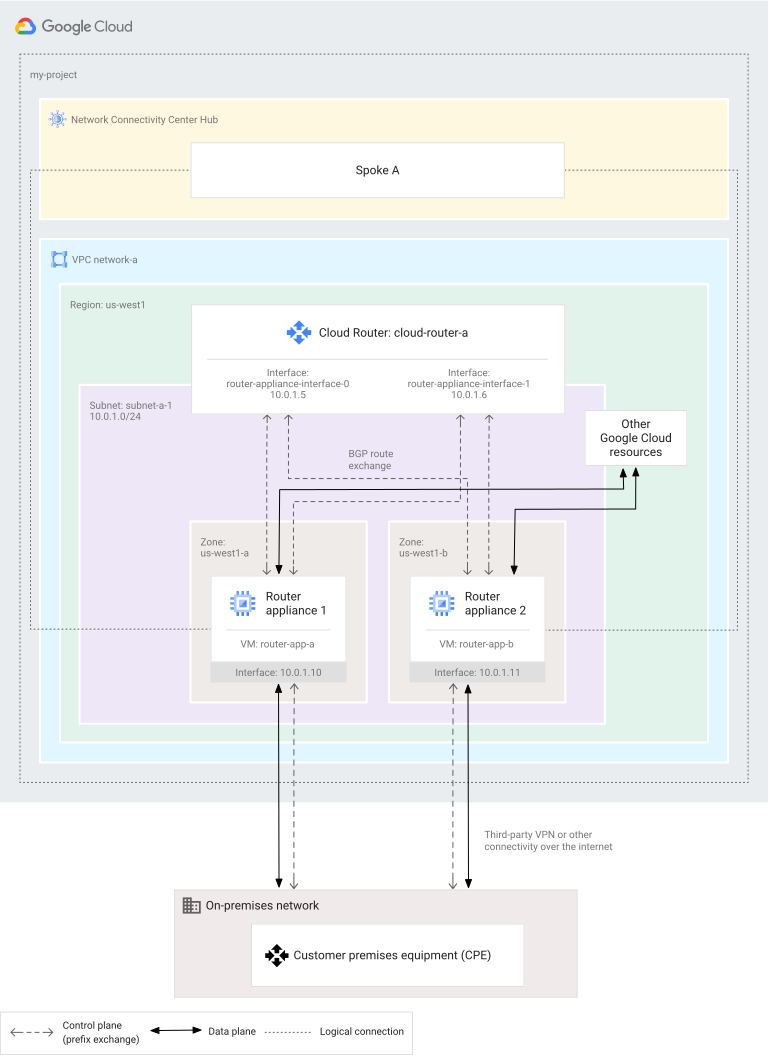](https://docs.cloud.google.com/static/network-connectivity/docs/network-connectivity-center/images/creating-router-appliance-bgp-sessions.svg) Creating BGP sessions for router appliance instances (click to enlarge)
## Before you begin
Before you get started, review the following sections.
### Create or select a project
To make it easier to configure NCC, start by identifying a valid
project.
1. If you are using the Google Cloud CLI, set your project
ID by using the
[`gcloud config set` command](https://docs.cloud.google.com/sdk/gcloud/reference/config/set).
```
gcloud config set project PROJECT_ID
```
Replace `PROJECT_ID` with your unique project ID.
The gcloud CLI instructions on this page assume that you have set your project ID.
2. To confirm that you set the project ID correctly, use the
[`gcloud config list` command](https://docs.cloud.google.com/sdk/gcloud/reference/config/list).
```
gcloud config list --format='text(core.project)'
```
### Enable the Network Connectivity API
Before you can perform *any* tasks using NCC, you must enable the
Network Connectivity API.
### Console
To enable the Network Connectivity API:
1. In the Google Cloud console, go to the **Network Connectivity Center** page.
[Go to Network Connectivity Center](https://console.cloud.google.com/hybrid/hubs/list)
2. Click **Enable**.
Alternatively, you can enable the API by
using the
[Google Cloud console API Library](https://console.cloud.google.com/apis/library?project=_),
as described in [Enabling APIs](https://docs.cloud.google.com/apis/docs/getting-started#enabling_apis).
### Get access
To work with NCC, you need the permissions described in
[Roles and permissions](https://docs.cloud.google.com/network-connectivity/docs/network-connectivity-center/concepts/access-control).
When you configure NCC, you also work with Google Cloud
resources such as VPC networks, subnets,
and firewall rules. For more information about the permissions you need to work
with these resources, see the
[Compute Engine access control documentation](https://docs.cloud.google.com/compute/docs/access).
### IP addresses and router appliance instances
To set up a router appliance instance, you must establish peering between the
instance and the Cloud Router. To set up peering, the VM must use an
RFC 1918 internal IP address. You cannot peer these two resources if the VM
uses a different type of address.
For information about how to view a VM's IP addresses, see the following
documents:
- [View the network configuration for an instance](https://docs.cloud.google.com/compute/docs/instances/view-network-properties)
- [Viewing IP addresses not attached to a VM instance](https://docs.cloud.google.com/sdk/gcloud/reference/compute/addresses/list)
For definitions and detailed information about IP address types, see
[IP addresses](https://docs.cloud.google.com/vpc/docs/ip-addresses).
#### Reserve a static internal IP address (recommended)
We recommend that you give your router appliance instance a static internal IP
address so that the address doesn't change during reboot. If the address
changes, BGP peering fails.
You have several options for assigning a reserved IP address. You can reserve
the IP address in advance. Alternatively, you can reserve the IP address when
you create the VM. If you mistakenly give the VM an ephemeral address, you can
later convert the address into a static address. For more information
about static IP addresses, see
[Reserving a static internal IP address](https://docs.cloud.google.com/vpc/docs/reserve-static-internal-ip-address).
#### IP addresses for BGP peering
A router appliance instance uses its internal IP address to
peer with the Cloud Router. The instance does *not* use a link-local
address (such as `169.254.x.x`) for BGP peering.
Similarly, the Cloud Router uses two RFC 1918 internal IP addresses to
peer with the router appliance instance, one address for each interface.
These IP addresses can be manually or automatically assigned from the subnet
that contains both the router appliance instance interface and the
Cloud Router interface.
## Create VPC resources
The following sections describe how to create a VPC network and
subnet.
### Create a VPC network
If you haven't already, create a VPC network. Set
the network's
[dynamic routing mode](https://docs.cloud.google.com/vpc/docs/create-modify-vpc-networks#switch-dynamic-routing) to `global`.
For more information about creating VPC networks, see
[Create networks](https://docs.cloud.google.com/vpc/docs/create-modify-vpc-networks#creating_networks).
### Console
To create a custom VPC network using the Google Cloud console,
see
[Creating a custom mode network](https://docs.cloud.google.com/vpc/docs/create-modify-vpc-networks#create-custom-network).
Make sure to set **Dynamic routing mode** to **Global** . If you want to
follow the naming conventions used in the sample configuration, call your
network `network-a`.
### gcloud
To create a custom VPC network, use the
[`gcloud compute networks create` command](https://docs.cloud.google.com/sdk/gcloud/reference/compute/networks/create).
```
gcloud compute networks create NETWORK \
--subnet-mode custom \
--bgp-routing-mode global
```
Replace `NETWORK` with the name of the VPC
network---for example, `network-a`.
### API
To create a custom VPC network by using the
Compute Engine API, see
[Create and manage VPC networks](https://docs.cloud.google.com/vpc/docs/create-modify-vpc-networks#api_1).
### Create a subnet
Create one subnet in `network-a` to contain the VM instances
used as router appliance instances.
### Console
To add a subnet using the Google Cloud console, see
[Adding subnets](https://docs.cloud.google.com/vpc/docs/create-modify-vpc-networks#add-subnets).
If you want to follow the naming conventions used in the sample
configuration, use the following values:
- **Name** : `subnet-a-1`
- **Region** : `us-west1`
- **Range** : `10.0.1.0/24`
### gcloud
To create a VPC subnet, use the
[`gcloud compute networks subnets create` command](https://docs.cloud.google.com/sdk/gcloud/reference/compute/networks/subnets/create).
```
gcloud compute networks subnets create SUBNET \
--network=NETWORK \
--region=REGION \
--range=RANGE
```
Replace the following:
- `SUBNET`: the name of the subnet that contains the router appliance VM---for example, `subnet-a-1`
- `NETWORK`: the network that contains the subnet---for example, `network-a`
- `REGION`: the region that contains the subnet---for example, `us-west1`
- `RANGE`: the IP range of the subnet in CIDR notation---for example, `10.0.1.0/24`
### API
To create a VPC subnet by using the Compute Engine API,
see [Create and manage VPC networks](https://docs.cloud.google.com/vpc/docs/create-modify-vpc-networks#api_5).
## Create router appliance VMs
Create the Compute Engine VMs that act as router appliance instances. The
sample configuration uses two VMs, `router-app-a` and `router-app-b`.
At a high level, you create a router appliance image by creating a VM that
uses a network virtual appliance image. This image can be any of the
following:
- A solution provided by a
[supported NCC partner](https://docs.cloud.google.com/network-connectivity/docs/network-connectivity-center/partners)
- A custom image, such as an image that you created
> [!NOTE]
> **Note:** If you are using an image from a vendor, see your vendor's documentation.
For more information about specifying images, see the following resources:
- [Images overview](https://docs.cloud.google.com/compute/docs/images)
- [Image families best practices](https://docs.cloud.google.com/compute/docs/images/image-families-best-practices)
- [Create, delete, and deprecate
custom images](https://docs.cloud.google.com/compute/docs/images/create-delete-deprecate-private-images)
For detailed information about creating VMs,
see [Create and start a VM instance](https://docs.cloud.google.com/compute/docs/instances/create-start-instance).
The examples in this section assume that you have reserved IP addresses for
the router appliance instance. For more information, see
[IP addresses and router appliance instances](https://docs.cloud.google.com/network-connectivity/docs/network-connectivity-center/how-to/creating-router-appliances#ip-recommendations).
### Console
To create the two VMs shown in the sample configuration, see
[Create and start a VM instance](https://docs.cloud.google.com/compute/docs/instances/create-start-instance).
When you create the VM, make the following choices:
- If you want to follow the naming conventions used in the sample
configuration, use the following values:
- **Name** : `router-app-a` or `router-app-b`
- **Region** :`us-west1`
- **Zone** : `us-west1-a` or `us-west1-b`
- To select an image, go the **Boot disk** area of the page, click
**Change**, and navigate to the appropriate image for the VM.
- Expand **Advanced options** , and then expand **Networking**. Use the
following values:
- Under **IP forwarding** , select **Enable**.
- Under **Network interfaces** , select **Add a Network Interface** , and fill in the following fields:
- Select the **Subnet** where you want to locate the router appliance instance---for example, `subnet-a-1`.
- Under **Primary internal IP** , select the reserved RFC 1918 internal IP address that you want to use---for example, `10.0.1.10`.
- Under **Network Service Tier** , select **Premium** ; this [choice](https://docs.cloud.google.com/network-tiers/docs/overview) maximizes the extent to which traffic uses Google's network.
### gcloud
To create the two router appliance VMs shown in the sample configuration,
use the
[`gcloud compute instances create` command](https://docs.cloud.google.com/sdk/gcloud/reference/compute/instances/create).
Use the command twice, once to create `router-app-a` and again to create
`router-app-b`.
The following sample snippet assigns the VM a static internal IP address and
a static external IP address. It also specifies a vendor-provided image to
use for the VM.
```
gcloud compute instances create INSTANCE_NAME \
--project=PROJECT \
--zone=ZONE \
--machine-type=MACHINE_TYPE \
--network-tier=NETWORK_TIER \
--network-interface=[subnet=SUBNET,private-network-ip=INTERNAL_IP_ADDRESS] \
--can-ip-forward \
--image-project=IMAGE_PROJECT \
--image=IMAGE
```
Replace the following:
- `INSTANCE_NAME`: the name of the VM that acts as a router appliance instance---for example, `router-app-a` or `router-app-b`
- `PROJECT`: the name of the project that contains the router appliance VMs---for example, `my-project`
- `ZONE`: the Google Cloud zone that the VM is located in---for example, `us-west1-a`
- `MACHINE_TYPE`: the machine type resource to use for the VM---for example, `n1-standard-2`
- `NETWORK_TIER`: when creating the router appliance VMs, set the [network tier](https://docs.cloud.google.com/network-tiers/docs/overview) to `premium`; this choice maximizes the extent to which traffic uses Google's network
- `SUBNET`: the subnet assigned to the primary network interface for the VM---for example, `subnet-a-1`
- `INTERNAL_IP_ADDRESS`: the RFC 1918 internal IP address that is assigned to the VM interface that connects to the Cloud Router---for example, `10.0.1.10`
- `IMAGE_PROJECT`: the name of the project that contains the image specified in the `image` field---for example, `debian-cloud`
- `IMAGE`: the name of the image to install---for example, `debian-10-buster-v20210217`
### API
To create the two router appliance VMs shown in the sample configuration,
use the
[`compute.instances.insert` method](https://docs.cloud.google.com/compute/docs/reference/rest/v1/instances/insert).
Use the method twice, once to create `router-app-a` and again to create
`router-app-b`.
The following sample snippet assigns the VM a static internal IP address and
a static external IP address. It also specifies a vendor-provided image to
use for the VM.
```
POST https://compute.googleapis.com/compute/v1/projects/PROJECT/zones/ZONE/instances
{
"machineType": "zones/ZONE/machineTypes/MACHINE_TYPE",
"name": "INSTANCE_NAME",
"canIpForward": "true",
"networkInterfaces": [{
"subnetwork": "regions/REGION/subnetworks/SUBNET",
"networkIP": "INTERNAL_IP_ADDRESS",
"accessConfigs": [{
"networkTier": "NETWORK_TIER,
}]
}],
"disks": [{
"initializeParams": {
"sourceImage": "projects/IMAGE_PROJECT/global/images/IMAGE"
},
"boot": true
}]
}
```
Replace the following:
- `PROJECT`: the name of the project that contains the router appliance VMs---for example, `my-project`
- `ZONE`: the Google Cloud zone that the VM is located in---for example, `us-west1-a`
- `MACHINE_TYPE`: the machine type resource to use for the VM---for example, `zones/us-west1-a/machineTypes/n1-standard-2`
- `INSTANCE_NAME`: the name of the VM---for example, `router-app-a` or `router-app-b`
- `REGION`: the region that contains the VM---for example, `us-west1`
- `SUBNET`: the subnet assigned to the primary network interface for the VM---for example, `regions/us-west1/subnetworks/subnet-a-1`
- `INTERNAL_IP_ADDRESS`: the RFC 1918 internal IP address that is assigned to the VM; configure the address for the VM interface that connects to the Cloud Router---for example, `10.0.1.10`
- `NETWORK_TIER`: when creating the router appliance VMs, set the [network tier](https://docs.cloud.google.com/network-tiers/docs/overview) to `premium`; this choice maximizes the extent to which traffic uses Google's network
- `IMAGE_PROJECT`: the name of the project that contains the image that you specify when creating the VM---for example, `debian-cloud`
- `IMAGE`: the name of the image to use when creating the VM---for example, `debian-10-buster-v20210217`
## Create a firewall rule to allow BGP
Create a firewall rule that allows BGP traffic to `network-a` on
TCP port `179`.
Make sure to also create specific firewall rules to allow traffic to flow to
the network virtual appliance (NVA).
For more information about firewall commands, see
[Use VPC firewall rules](https://docs.cloud.google.com/vpc/docs/using-firewalls).
### Console
To create a VPC firewall rule using the
Google Cloud console, see
[Use VPC firewall rules](https://docs.cloud.google.com/vpc/docs/using-firewalls#console).
### gcloud
To create a VPC firewall rule by using the
Google Cloud CLI, see
[Use VPC firewall rules](https://docs.cloud.google.com/vpc/docs/using-firewalls#gcloud).
### API
To create a VPC firewall rule by using the
Compute Engine API, see
[Use VPC firewall rules](https://docs.cloud.google.com/vpc/docs/using-firewalls#api).
## Create NCC resources
Before you can use a router appliance VM, you must create the required
NCC resources, including a Router appliance spoke.
### Create a hub
Before you can create NCC spokes, you must create a hub.
### Console
1. In the Google Cloud console, go to the **Network Connectivity Center** page.
[Go to Network Connectivity Center](https://console.cloud.google.com/hybrid/hubs/list)
2. In the project menu, select a project.
3. Enter a **Hub name**.
4. Enter an optional **Description**.
5. Verify the **Project ID**. If the project ID is incorrect, select a
different project by using the menu at the top of the screen.
6. Click **Continue**.
7. The console displays a form that lets you create a spoke. To fill it out
now, use the steps described in
[Create a Router appliance spoke](https://docs.cloud.google.com/network-connectivity/docs/network-connectivity-center/how-to/creating-router-appliances#create-spoke).
8. Click **Done**.
### gcloud
To create a hub, use the
[`gcloud network-connectivity hubs create` command](https://docs.cloud.google.com/sdk/gcloud/reference/network-connectivity/hubs/create).
```
gcloud network-connectivity hubs create HUB_NAME \
--description="DESCRIPTION" \
--labels="KEY"="VALUE"
```
Replace the following values:
- `HUB_NAME`: the name of the new hub
- `DESCRIPTION`: optional text that describes the hub
- `KEY`: the key in the key-value pair for the optional label text
- `VALUE`: the value in the key-value pair for the optional label text
### API
To create a hub, use the
[`networkconnectivity.hubs.create` method](https://docs.cloud.google.com/network-connectivity/docs/reference/networkconnectivity/rest/v1/projects.locations.global.hubs/create).
```
POST https://networkconnectivity.googleapis.com/v1/projects/PROJECT_ID/locations/global/hubs
{
"name":"HUB_NAME",
"description":"DESCRIPTION",
"labels": {
"KEY": "VALUE"
}
}
```
Replace the following values:
- `PROJECT_ID`: the project ID of the project that contains the new hub
- `HUB_NAME`: the name of the new hub
- `DESCRIPTION`: optional text that describes the hub
- `KEY`: the key in the key-value pair for the optional label text
- `VALUE`: the value in the key-value pair for the optional label text
### Create a Router appliance spoke
Create a Router appliance spoke that uses the two router appliance
instances that you just created. Creating a spoke is required for enabling BGP
peering between the router appliance instance and the Cloud Router,
which you create in the next step.
For more information about how to create a spoke, see
[Work with hubs and spokes](https://docs.cloud.google.com/network-connectivity/docs/network-connectivity-center/how-to/working-with-hubs-spokes#create-ra-spoke).
### Console
**Enter basic spoke details**
1. In the Google Cloud console, go to the **Network Connectivity Center** page.
[Go to Network Connectivity Center](https://console.cloud.google.com/hybrid/hubs/list)
2. In the project menu, select a Google Cloud project.
3. Click the **Spokes** tab.
4. Click **Add spokes**.
5. In the **New spoke** form, set the **Spoke type**.
6. Enter a **Spoke name** and optionally, a **Description**.
7. Select the **Region** field for the new spoke.
8. Under **Site-to-site data transfer** , select **On** or **Off** . If the region you selected does not support data transfer, the field is disabled. For more information about this use case, see [Site-to-site data transfer overview](https://docs.cloud.google.com/network-connectivity/docs/network-connectivity-center/concepts/data-transfer).
9. In the **VPC network** list, select a network. If you have more than one spoke that uses the data transfer feature, all of these spokes must be in the same VPC network. So if you have already created a spoke that uses data transfer, the **VPC network** value is prepopulated and cannot be changed.
**Enter router appliance details**
1. Set **Spoke type** to **Router appliance**.
2. Select the **Region** for the spoke.
3. Choose a router appliance instance:
1. Click **Add instance**.
2. From the **Instances** menu, select an existing router appliance instance.
4. To add more router appliance instances to this spoke, repeat the preceding step. When you are finished, click **Done** and continue to **Save your spoke**.
**Save your spoke**
1. If you want to add more spokes, click **Add spoke** and begin the process again, starting with entering a **Spoke name**.
2. When you are finished adding spokes, click **Create** . The **NCC** page updates to show details about the spokes that you created.
### gcloud
To create a Router appliance spoke, use the
[`gcloud network-connectivity spokes linked-router-appliances create` command](https://docs.cloud.google.com/sdk/gcloud/reference/network-connectivity/spokes/linked-router-appliances/create).
The following sample snippet creates a spoke that contains two router
appliance instances. In this sample, the spoke does not use the
site-to-site data transfer feature. (To enable data transfer, add one more
flag: `--site-to-site-data-transfer`.)
```
gcloud network-connectivity spokes linked-router-appliances create NAME \
--hub="HUB_NAME" \
--description="DESCRIPTION" \
--router-appliance=instance="ROUTER_APPLIANCE_URI",ip=IP_ADDRESS \
--router-appliance=instance="ROUTER_APPLIANCE_URI_2",ip=IP_ADDRESS_2 \
--region=REGION \
--labels="KEY"="VALUE"
```
Replace the following values:
- `NAME`: the name of the spoke
- `HUB_NAME`: the name of the hub that you are attaching the spoke to
- `DESCRIPTION`: optional text that describes the spoke---for example, `us-vpn-spoke`
- `ROUTER_APPLIANCE_URI`: the URI of the first router appliance instance---for example,
```
https://www.googleapis.com/compute/projects/PROJECT_ID/zones/ZONE/instances/INSTANCE_NAME
```
- `IP_ADDRESS`: the internal IP address of the first router appliance instance
- `ROUTER_APPLIANCE_URI_2`: the URI of the second router appliance instance
- `IP_ADDRESS_2`: the internal IP address of the second router appliance instance
- `REGION`: the Google Cloud region where you want to locate the spoke---for example, `us-west1`
- `KEY`: the key in the key-value pair for the optional label text
- `VALUE`: the value in the key-value pair for the
optional label text
For example, the following command creates a router appliance spoke that
uses `router-app-a` and `router-app-b` as its underlying resources:
```
gcloud network-connectivity spokes linked-router-appliances create my-spoke \
--hub=my-hub \
--description="Test spoke 1" \
--router-appliance=instance="https://www.googleapis.com/compute/v1/projects/my-project/zones/us-west1-a/instances/router-app-a",ip=10.0.1.10 \
--router-appliance=instance="https://www.googleapis.com/compute/v1/projects/my-project/zones/us-west1-b/instances/router-app-b",ip=10.0.1.11 \
--region=us-west1 \
--labels="environment"="test"
```
To create the same spoke but enable data transfer, use the following
command:
```
gcloud network-connectivity spokes linked-router-appliances create my-spoke \
--hub=my-hub \
--description="Test spoke 1" \
--router-appliance=instance="https://www.googleapis.com/compute/v1/projects/my-project/zones/us-west1-a/instances/router-app-a",ip=10.0.1.10 \
--router-appliance=instance="https://www.googleapis.com/compute/v1/projects/my-project/zones/us-west1-b/instances/router-app-b",ip=10.0.1.11 \
--region=us-west1 \
--labels="environment"="test"
--site-to-site-data-transfer
```
### API
To create a Router appliance spoke, use the
[`networkconnectivity.spokes.create` method](https://docs.cloud.google.com/network-connectivity/docs/reference/networkconnectivity/rest/v1/projects.locations.spokes/create).
The following sample snippet creates a spoke that contains two
[router appliance instances](https://docs.cloud.google.com/network-connectivity/docs/reference/networkconnectivity/rest/v1/projects.locations.spokes#RouterApplianceInstance).
Each instance is included in the `linkedRouterApplianceInstances.instances`
array.
```
POST https://networkconnectivity.googleapis.com/v1/projects/PROJECT_ID/locations/REGION/spokes/SPOKE_NAME
{
"hub": "HUB_URI",
"labels": {"KEY": "VALUE"},
"linkedRouterApplianceInstances": {
"instances": [
{
"virtualMachine": "ROUTER_APPLIANCE_URI",
"ipAddress": INTERNAL_IP_ADDRESS,
},
{
"virtualMachine": "ROUTER_APPLIANCE_URI_2,
"ipAddress": INTERNAL_IP_ADDRESS_2,
}
],
"siteToSiteDataTransfer": BOOLEAN
}
}
```
Replace the following values:
- `PROJECT_ID`: the project ID of your project
- `REGION`: the Google Cloud region where you want to locate the spoke---for example, `us-west1`
- `SPOKE_NAME`: the name you want to give the spoke
- `HUB_URI`: the URI of the hub that you are attaching the spoke to---for example,
```
http://networkconnectivity.googleapis.com/v1/projects/PROJECT_NAME/locations/global/hubs/HUB_NAME
```
- `KEY`: the key in the key-value pair for the optional label text
- `VALUE`: the value in the key-value pair for the optional label text
- `ROUTER_APPLIANCE_URI`: the URI of the first router appliance instance---for example,
```
https://www.googleapis.com/compute/projects/PROJECT_ID/zones/ZONE/instances/INSTANCE_NAME
```
- `IP_ADDRESS`: the internal IP address of the first router appliance instance
- `ROUTER_APPLIANCE_URI_2`: the URI of the second router appliance instance
- `IP_ADDRESS_2`: the internal IP address of the second router appliance instance
- `BOOLEAN`: a value that determines whether site-to-site
data transfer is enabled for this spoke
For example, to create a spoke that uses `router-app-a` and `router-app-b`
as its underlying resources, the body of your request should be structured
as follows:
```
{
"hub": "http://networkconnectivity.googleapis.com/v1/projects/my-project/locations/global/hubs/my-hub",
"labels": {
"environment" : "test"
},
"linkedRouterApplianceInstances": {
"instances": [
{
"virtualMachine": "https://www.googleapis.com/compute/v1/projects/my-project/zones/us-west1-a/instances/router-app-a",
"ipAddress": "10.0.1.10",
},
{
"virtualMachine": "https://www.googleapis.com/compute/v1/projects/my-project/zones/us-west1-b/instances/router-app-b",
"ipAddress": "10.0.1.11",
}
],
"siteToSiteDataTransfer": true
}
}
```
## Set up a Cloud Router
Router appliance uses a Cloud Router to exchange routes with your
VPC network. For this reason, you must create a
Cloud Router and complete a few other setup tasks.
### Create a Cloud Router
Create the resource in the same network and region where the router
VM is. In the sample configuration, these resources
are `network-a` and `us-west1`.
For more information, see
[Create a Cloud Router](https://docs.cloud.google.com/network-connectivity/docs/router/how-to/create-router-vpc-on-premises-network).
### Console
To create a Cloud Router in the Google Cloud console, use one of the following approaches:
- Use the **Cloud Router** page, as described in
[Create a Cloud Router](https://docs.cloud.google.com/network-connectivity/docs/router/how-to/create-router-vpc-on-premises-network#create_a).
- Use the **Network Connectivity Center** page. The advantage
of this approach is that it lets you create the router, the interfaces, and
the BGP sessions at the same time. For more information about completing all of
these steps together, see
[Configure BGP peering on the Cloud Router](https://docs.cloud.google.com/network-connectivity/docs/network-connectivity-center/how-to/creating-router-appliances#create-peers).
### gcloud
To create a Cloud Router, use the
[`gcloud compute routers create` command](https://docs.cloud.google.com/sdk/gcloud/reference/compute/routers/create).
```
gcloud compute routers create NAME \
--region=REGION \
--network=NETWORK \
--asn=ASN \
--project=PROJECT_ID
```
Replace the following:
- `NAME`: the name of the Cloud Router---for example, `cloud-router-a`
- `REGION`: the region that contains the Cloud Router---for example, `us-west1`
- `NETWORK`: the VPC network that contains the Cloud Router---for example, `network-a`
- `ASN`: the autonomous system number (ASN) for the Cloud Router---this ASN must be a 16-bit or 32-bit private ASN as defined in [RFC 6996](https://tools.ietf.org/html/rfc6996)---for example, `65000`
- `PROJECT_ID`: the project ID for the Cloud Router---for example, `my-project`
### API
To create a Cloud Router, use the
[`compute.routers.insert` method](https://docs.cloud.google.com/compute/docs/reference/rest/v1/routers/insert).
```
POST https://compute.googleapis.com/compute/v1/projects/PROJECT_ID/regions/REGION/routers
{
"name": "NAME",
"network": "NETWORK",
"bgp": {
"asn": ASN
}
}
```
Replace the following:
- `PROJECT_ID`: the project ID for the Cloud Router---for example, `my-project`
- `REGION`: the region that contains the Cloud Router---for example, `us-west1`
- `NAME`: the name of the Cloud Router---for example, `cloud-router-a`
- `NETWORK`: the URI of the VPC network that contains the Cloud Router---for example, `/global/networks/network-a`
- `ASN`: the autonomous system number (ASN) for the Cloud Router---this ASN must be a 16-bit or 32-bit private ASN as defined in [RFC 6996](https://tools.ietf.org/html/rfc6996)---for example, `65000`
### Create two redundant interfaces on the Cloud Router
Create two redundant Cloud Router interfaces that, in the sample
configuration, are associated with `subnet-a-1`.
> [!NOTE]
> **Note:** You must create the primary interface before you create the redundant interface.
The Cloud Router interface uses a regional internal IP address.
If you explicitly specify the internal IP address for the interface, the
IP address must belong to the subnet's primary IP address range. It must not
already be in use by another resource, such as a VM or a different
Cloud Router interface. To reserve an IP address from the
subnet in advance, create an address resource and then use the
reserved IP address for the Cloud Router interface.
There are no Google Cloud console instructions for this step
because when you create a BGP peer by using the Google Cloud console,
the interfaces are created for you automatically.
### gcloud
To create the two redundant Cloud Router interfaces shown in the
sample configuration, use the
[`gcloud compute routers add-interface` command](https://docs.cloud.google.com/sdk/gcloud/reference/compute/routers/add-interface).
Use the command twice, once to create `router-appliance-interface-0` and
again to create `router-appliance-interface-1`.
If you don't specify the `--ip-address` option, Google tries to find a free
IP address from the subnet's primary IP range to assign to the interface.
1. Create the first Cloud Router interface:
```
gcloud compute routers add-interface NAME \
--interface-name=INTERFACE_NAME \
--ip-address=IP_ADDRESS \
--subnetwork=SUBNET \
--region=REGION \
--project=PROJECT_ID
```
2. Create the redundant Cloud Router interface:
```
gcloud compute routers add-interface NAME \
--interface-name=INTERFACE_2_NAME \
--ip-address=IP_ADDRESS \
--subnetwork=SUBNET \
--redundant-interface=INTERFACE_NAME \
--region=REGION \
--project=PROJECT_ID
```
Replace the following:
- `NAME`: the name of the Cloud Router to update---for example, `cloud-router-a`
- `INTERFACE_NAME`: the name of the interface---for example, `router-appliance-interface-0`
- `IP_ADDRESS`: the RFC 1918 internal IP address to use for the interface---for example, `10.0.1.5` or `10.0.1.6`
- `SUBNET`: the subnet that includes the internal IP address---for example, `subnet-a-1`
- `INTERFACE_2_NAME`: the redundant Cloud Router interface that peers with the same router appliance instance as the primary interface---for example, `router-appliance-interface-1`
- `REGION`: the Google Cloud region where the Cloud Router is---for example, `us-west1`
- `PROJECT_ID`: the project ID for the Cloud Router---for example, `my-project`
- The following command creates the first interface on
the Cloud Router as described in the sample configuration:
```
gcloud compute routers add-interface cloud-router-a \
--interface-name=router-appliance-interface-0 \
--ip-address=10.0.1.5 \
--subnetwork=subnet-a-1 \
--region=us-west1 \
--project=my-project
```
- The following command creates the redundant interfaces on
the Cloud Router as described in the sample configuration:
```
gcloud compute routers add-interface cloud-router-a \
--interface-name=router-appliance-interface-1 \
--ip-address=10.0.1.6 \
--subnetwork=subnet-a-1 \
--redundant-interface=router-appliance-interface-0 \
--region=us-west1 \
--project=my-project
```
### API
To create the two redundant Cloud Router interfaces shown in the
sample configuration, use the
[`compute.routers.patch` method](https://docs.cloud.google.com/compute/docs/reference/rest/v1/routers/patch).
Use the method twice, once to create `router-appliance-interface-0` and
again to create `router-appliance-interface-1`.
If you don't specify the `privateIpAddress` option, Google tries to find a
free IP address from the subnet's primary IP range to assign to the
interface.
1. Create the first Cloud Router interface:
```
"PATCH
https"://www.googleapis.com/compute/v1/projects/PROJECT_ID/regions/REGION/routers/NAME
{
"region":"REGION",
"interfaces":[
{
"name":"INTERFACE_NAME",
"privateIpAddress:"IP_ADDRESS",
"subnetwork": "https":"//www.googleapis.com/compute/v1/projects/PROJECT_ID/regions/REGION/subnetworks/SUBNET"
}
]
}
```
2. Create the redundant Cloud Router interface:
```
"PATCH
https"://www.googleapis.com/compute/v1/projects/PROJECT_ID/regions/REGION/routers/NAME
{
"region":"REGION",
"interfaces":[
{
"name":"INTERFACE_NAME_1",
"privateIpAddress:"IP_ADDRESS",
"subnetwork": "https://www.googleapis.com/compute/v1/projects/PROJECT_ID/regions/REGION/subnetworks/SUBNET"
},
{
"name":"INTERFACE_NAME_2",
"privateIpAddress:"IP_ADDRESS",
"subnetwork": "https://www.googleapis.com/compute/v1/projects/PROJECT_ID/regions/REGION/subnetworks/SUBNET",
"redundantInterface": "INTERFACE_NAME_1"
}
]
}
```
Replace the following:
- `PROJECT_ID`: the project ID for the Cloud Router---for example, `my-project`
- `REGION`: the Google Cloud region where the Cloud Router is---for example, `us-west1`
- `NAME`: the name of the Cloud Router to update---for example, `cloud-router-a`
- `NETWORK`: the VPC network that contains the Cloud Router---for example,`network-a`
- `INTERFACE_NAME_1`: the name of the primary interface---for example, `router-appliance-interface-0`
- `SUBNET`: the URL for the subnet that contains the RFC 1918 internal IP address
- `IP_ADDRESS`: the internal IP address to use for the interface---for example, `10.0.1.5` or `10.0.1.6`
- `INTERFACE_NAME_2`: the name of the redundant Cloud Router interface---for example, `router-appliance-interface-1`
- The following command creates the first interface on `cloud-router-a` as
described in the sample configuration:
```
"PATCH https"://www.googleapis.com/compute/v1/projects/my-project/regions/us-west1/routers/cloud-router-a
{
"region":"us-west1",
"interfaces":[
{
"name":"router-appliance-interface-0",
"privateIpAddress:"10.0.1.5",
"subnetwork": "https://www.googleapis.com/compute/v1/projects/my-project/regions/us-west1/subnetworks/>"
}
]
}
```
- The following command creates the redundant interfaces on `cloud-router-a`
as described in the sample configuration:
```
"PATCH https"://www.googleapis.com/compute/v1/projects/my-project/regions/us-west1/routers/cloud-router-a
{
"region":"us-west1",
"interfaces":[
{
"name":"router-appliance-interface-0",
"privateIpAddress:"10.0.1.5",
"subnetwork": "https://www.googleapis.com/compute/v1/projects/my-project/regions/us-west1/subnetworks/subnet-a-1"
},
{
"name":"router-appliance-interface-0",
"privateIpAddress:"10.0.1.6",
"subnetwork": "https://www.googleapis.com/compute/v1/projects/my-project/regions/us-west1/subnetworks/subnet-a-1",
"redundantInterface": "router-appliance-interface-0"
}
]
}
```
### Configure BGP peering on the Cloud Router
For each router appliance instance, you must create two BGP peers on the
Cloud Router---one for each Cloud Router interface.
The BGP peer IP address must be the primary internal IP address for the
VM that is configured as a router appliance instance.
#### Create BGP peers for `router-app-a`
This section describes how to create two BGP peers for the router appliance
instance named `router-app-a` in the sample configuration. The next section
describes how to create two BGP peers on `router-app-b`.
The following example shows how to configure `router-app-a` as a BGP peer on
both interfaces of Cloud Router `cloud-router-a`.
### Console
1. Go to the **Network Connectivity Center** page.
[Go to Network Connectivity Center](https://console.cloud.google.com/hybrid/hubs/list)
2. In the project pull-down menu, select a project.
3. Click the **Spokes** tab.
4. In the **Spoke name** column, select a spoke to view the **Spoke details** page.
1. In the **Name** column, locate `router-app-a`.
Click the expand icon to display the **Configure BGP session**
links. Click either of these links. In response, the system
displays the **Configure Cloud Router and BGP sessions**
panel.
1. In the **Cloud Router** section, do one of the following:
- To select an existing Cloud Router, click **Use existing** . Use the **Cloud Router** field to identify the appropriate resource, and then click **Select and continue**.
- To create a Cloud Router on the **Network Connectivity Center** page, click **Create new** , and follow the prompts to create the Cloud Router. Then click **Create and continue**.
2. Under **BGP Sessions** , set up the two BGP sessions. Complete the following steps twice, once for each session:
1. Click **Edit BGP session**.
2. Fill in the form by entering a **Name** , a **Peer ASN** , and an **Advertised route priority (MED)** . Click **Save and continue**.
3. Click **Create**.
### gcloud
To create BGP peers on the Cloud Router for `router-app-a`, use the
[`gcloud compute routers add-bgp-peer` command](https://docs.cloud.google.com/sdk/gcloud/reference/compute/routers/add-bgp-peer).
Use the command twice---once to create the first BGP peer and again to
create the second BGP peer.
1. Create the first BGP peer:
```
gcloud compute routers add-bgp-peer NAME \
--peer-name=PEER_NAME \
--interface=INTERFACE \
--peer-ip-address=PEER_IP_ADDRESS \
--peer-asn=PEER_ASN \
--instance=ROUTER_APPLIANCE \
--instance-zone=ROUTER_APPLIANCE_ZONE \
--region=REGION
```
2. Create the second BGP peer:
```
gcloud compute routers add-bgp-peer NAME \
--peer-name=PEER_NAME \
--interface=INTERFACE \
--peer-ip-address=PEER_IP_ADDRESS \
--peer-asn=PEER_ASN \
--instance=ROUTER_APPLIANCE \
--instance-zone=ROUTER_APPLIANCE_ZONE \
--region=REGION
```
Replace the following:
- `NAME`: the name of the Cloud Router to update
- `PEER_NAME`: the name of the BGP peering session to establish with the router appliance instance
- `INTERFACE`: the name of the interface for this BGP peer
- `PEER_IP_ADDRESS`: the [internal IP
address](https://docs.cloud.google.com/vpc/docs/ip-addresses) of the peer router (the router appliance instance)---this address must match the primary internal IP address for the VM's primary network interface (`nic0`)
- `PEER_ASN`: the BGP autonomous system number (ASN) for this BGP peer---this ASN must be a 16-bit or 32-bit private ASN as defined in [RFC 6996](https://tools.ietf.org/html/rfc6996)
- `ROUTER_APPLIANCE`: the name of the VM acting as the router appliance instance
- `ROUTER_APPLIANCE_ZONE`: the zone where the VM acting as the router appliance instance is located
- `REGION`: the region where the VM acting as the router appliance instance is located
The following sample snippets show how to create both peers for
`router-app-a`:
```
gcloud compute routers add-bgp-peer cloud-router-a \
--peer-name=router-appliance-bgp-peer-router-app-a-0 \
--interface=router-appliance-interface-0 \
--peer-ip-address=10.0.1.10 \
--peer-asn=65001 \
--instance=router-app-a \
--instance-zone=us-west1-a \
--region=us-west1
```
```
gcloud compute routers add-bgp-peer cloud-router-a \
--peer-name=router-appliance-bgp-peer-router-app-a-1 \
--interface=router-appliance-interface-1 \
--peer-ip-address=10.0.1.10 \
--peer-asn=65001 \
--instance=router-app-a \
--instance-zone=us-west1-a \
--region=us-west1
```
### API
To create BGP peers on the Cloud Router for `router-app-a`, use the
[`compute.routers.patch` method](https://docs.cloud.google.com/compute/docs/reference/rest/v1/routers/patch).
Use the method twice---once to create the first BGP peer and again to
create the second BGP peer.
```
PATCH
https://compute.googleapis.com/compute/v1/projects/PROJECT_ID/regions/REGION/routers/NAME
{
"bgpPeers": [
{
"name": "PEER_NAME",
"interfaceName": "INTERFACE_NAME",
"ipAddress": "IP_ADDRESS",
"peerIpAddress": "PEER_IP_ADDRESS",
"routerApplianceInstance": "https://compute.googleapis.com/compute/v1/projects/PROJECT_ID/zone/ROUTER_APPLIANCE_ZONE/instances/ROUTER_APPLIANCE_INSTANCE",
"peerAsn": PEER_ASN,
}
{
"name": "PEER_NAME",
"interfaceName": "INTERFACE_NAME",
"ipAddress": "IP_ADDRESS",
"peerIpAddress": "PEER_IP_ADDRESS",
"routerApplianceInstance": "https://compute.googleapis.com/compute/v1/projects/PROJECT_ID/zone/ROUTER_APPLIANCE_ZONE/instances/ROUTER_APPLIANCE_INSTANCE",
"peerAsn": PEER_ASN
}
]
}
```
Replace the following:
- `PROJECT_ID`: the project ID for the Cloud Router
- `REGION`: the region where the VM acting as the router appliance instance is located
- `NAME`: the name of the Cloud Router to update
- `PEER_NAME`: the name of the BGP peering session to establish with the router appliance instance
- `INTERFACE_NAME`: the name of the Cloud Router interface to add the peer to
- `IP_ADDRESS`: the RFC 1918 internal IP address to use for the Cloud Router interface
- `PEER_IP_ADDRESS`: the internal IP address of the VM acting as a router appliance instance
- `ROUTER_APPLIANCE_INSTANCE`: the name in URL format for the VM acting as the router appliance instance
- `ROUTER_APPLIANCE_ZONE`: the zone where the VM acting as the router appliance instance is located
- `PEER_ASN`: the BGP autonomous system number (ASN) for this BGP peer---this ASN must be a 16-bit or 32-bit private ASN as defined in [RFC 6996](https://tools.ietf.org/html/rfc6996)
The following sample snippets show how to create both peers for
`router-app-a`:
```
PATCH
https://compute.googleapis.com/compute/v1/projects/my-project/regions/us-west1/routers/cloud-router-a
{
"bgpPeers": [
{
"name": "router-appliance-bgp-peer-router-app-a-0",
"interfaceName": "router-appliance-interface-0",
"ipAddress": "10.0.1.5",
"peerIpAddress": "10.0.1.10",
"routerApplianceInstance": "https://compute.googleapis.com/compute/v1/projects/my-project/zone/us-west1-a/instances/router-app-a",
"peerAsn": 65001,
}
{
"name": "router-appliance-bgp-peer-router-app-a-1",
"interfaceName": "router-appliance-interface-1",
"ipAddress": "10.0.1.6",
"peerIpAddress": "10.0.1.10",
"routerApplianceInstance": "https://compute.googleapis.com/compute/v1/projects/my-project/zone/us-west1-a/instances/router-app-a",
"peerAsn": 65001
}
]
}
```
#### Create BGP peers for `router-app-b`
As described previously, Cloud Router can establish BGP sessions
to multiple VMs configured as router appliance instances. These VMs must all
be in the same region. To create this configuration, you create additional
BGP peering sessions on the same Cloud Router interfaces.
The preceding section described how to set up BGP peering for `router-app-a`.
This section describes how to additionally configure `router-app-b` as
a BGP peer on both interfaces of Cloud Router `cloud-router-a`.
### Console
1. Go to the **Network Connectivity Center** page.
[Go to Network Connectivity Center](https://console.cloud.google.com/hybrid/hubs/list)
2. In the project pull-down menu, select a project.
3. Click the **Spokes** tab.
4. In the **Spoke name** column, select a spoke to view the **Spoke details** page.
1. In the **Name** column, locate `router-app-b`. Click the expand icon to display the **Configure BGP session** links. Click either of these links. In response, the system displays the **Configure Cloud Router and BGP sessions** panel.
1. In the **Cloud Router** section, do one of the following:
- To select an existing Cloud Router, click **Use existing** . Use the **Cloud Router** field to identify the appropriate resource, and then click **Select and continue**.
- To create a Cloud Router on the **Network Connectivity Center** page, click **Create new** , and follow the prompts to create the Cloud Router. Then click **Create and continue**.
2. Under **BGP Sessions** , set up the two BGP sessions. Complete the following steps twice, once for each session:
1. Click **Edit BGP session**.
2. Fill in the form by entering a **Name** , a **Peer ASN** , and an **Advertised route priority (MED)** . Click **Save and continue**.
3. Click **Create**.
### gcloud
To create two BGP peers on the Cloud Router for `router-app-b`, use
the
[`gcloud compute routers add-bgp-peer` command](https://docs.cloud.google.com/sdk/gcloud/reference/compute/routers/add-bgp-peer).
Use the command twice---once to create the first BGP peer and again to
create the second BGP peer.
- Sample configuration for the first BGP peer:
```
gcloud compute routers add-bgp-peer cloud-router-a \
--peer-name=router-appliance-bgp-peer-router-app-b-0 \
--interface=router-appliance-interface-0 \
--peer-ip-address=10.0.1.11 \
--peer-asn=65002 \
--instance=router-app-b \
--instance-zone=us-west1-b \
--region=us-west1
```
- Sample configuration for the second BGP peer:
```
gcloud compute routers add-bgp-peer cloud-router-a \
--peer-name=router-appliance-bgp-peer-router-app-b-1 \
--interface=router-appliance-interface-1 \
--peer-ip-address=10.0.1.11 \
--peer-asn=65002 \
--instance=router-app-b \
--instance-zone=us-west1-b \
--region=us-west1
```
### API
To create two BGP peers on the Cloud Router for `router-app-b`, use
the [`compute.routers.patch` method](https://docs.cloud.google.com/compute/docs/reference/rest/v1/routers/patch).
Use the method twice---once to create the first BGP peer and
again to create the second BGP peer.
```
PATCH
https://compute.googleaps.com/compute/v1/projects/my-project/regions/us-west1/routers/cloud-router-a
{
"bgpPeers": [
{
"name": "router-appliance-bgp-peer-router-app-b-0",
"interfaceName": "router-appliance-interface-0",
"ipAddress": "10.0.1.5",
"peerIpAddress": "10.0.1.11",
"routerApplianceInstance": "https://compute.googleapis.com/compute/v1/projects/my-project/zone/us-west1-b/instances/router-app-b",
"peerAsn": 65002,
}
{
"name": "router-appliance-bgp-peer-router-app-b-1",
"interfaceName": "router-appliance-interface-1",
"ipAddress": "10.0.1.6",
"peerIpAddress": "10.0.1.11",
"routerApplianceInstance": "https://compute.googleapis.com/compute/v1/projects/my-project/zone/us-west1-b/instances/router-app-b",
"peerAsn": 65002
}
]
}
```
## Configure BGP on the router appliance instance
To configure your router appliance instance for BGP connectivity to
the Cloud Router, refer to the vendor documentation
for your router appliance image.
### Use custom learned routes
Optionally, you can configure your router appliance instance to use custom
learned routes. When you configure custom learned routes,
Cloud Router behaves as if it learned the routes from the BGP
peer (the router appliance instance).
To use custom learned routes, complete the following steps:
1. Log in to your appliance. For each custom learned route that you want to
specify, configure a static route for that IP prefix with the next hop
set to the external network. This step is necessary because the router
appliance instance needs to know how to forward traffic that uses
the custom learned route.
2. Update the BGP session on your Cloud Router to use the
custom learned routes. Follow the steps described in
[Update an existing session to use custom learned routes](https://docs.cloud.google.com/network-connectivity/docs/router/how-to/configure-custom-learned-routes#add-routes-to-existing-session).
### Use MD5 authentication
If the router appliance image that you are using supports MD5 authentication,
you can optionally add authentication to your BGP peering sessions. For
information about using MD5 authentication with Cloud Router, see
[Use MD5 authentication](https://docs.cloud.google.com/network-connectivity/docs/router/how-to/use-md5-authentication).
## What's next
- To delete a router appliance instance, see [Delete router appliance instances](https://docs.cloud.google.com/network-connectivity/docs/network-connectivity-center/how-to/deleting-router-appliances).
- To view a list of partners whose solutions are integrated with NCC, see [NCC partners](https://docs.cloud.google.com/network-connectivity/docs/network-connectivity-center/partners).
- To view Router appliance monitoring and logging information, see [Viewing logs and metrics](https://docs.cloud.google.com/network-connectivity/docs/network-connectivity-center/how-to/viewing-logs-metrics).
- To find solutions for Router appliance issues, see [Troubleshooting](https://docs.cloud.google.com/network-connectivity/docs/network-connectivity-center/support/troubleshooting#troubleshooting-ra).
- To get details about the API and the gcloud CLI, see [APIs and reference](https://docs.cloud.google.com/network-connectivity/docs/network-connectivity-center/apis).