[Video](https://www.youtube.com/watch?v=XzGU02ycSvc)
Cross-Site Interconnect lets you establish reliable,
high-bandwidth Layer 2 connectivity between your on-premises network sites
by using [Google's global network](https://cloud.google.com/about/locations#network).
You can use Cross-Site Interconnect to expand your connectivity
globally, or add redundancy or capacity to your network.
## Before you use Cross-Site Interconnect
Ensure that you meet the following requirements:
- Be familiar with [Cloud Interconnect
terminology](https://docs.cloud.google.com/network-connectivity/docs/interconnect/concepts/terminology).
- Your network must physically meet Google's network in a [colocation
facility](https://docs.cloud.google.com/network-connectivity/docs/interconnect/concepts/cross-site-locations). You must provide your own routing equipment. Your on-premises router is typically located in the colocation facility. However, you can also extend your connection to a router outside of the colocation facility.
- In the colocation facility, your network devices must support the following
technical requirements:
- 10-Gbps circuits, single mode fiber, 10GBASE-LR (1310 nm), or 100-Gbps
circuits, single mode fiber, 100GBASE-LR4
> [!NOTE]
> **Note:** The maximum supported fiber length for 10GBASE-LR or 100GBASE-LR4 optics is 10 km. If your on-premises router is more than 10 km away from the Google demarcation, you must use a lit wavelength, [DWDM](https://www.wikipedia.org/wiki/Wavelength-division_multiplexing), or other managed circuit to complete your connection.
- 802.1Q VLANs, for cross-site networks that contain wire groups in VLAN mode
In addition, note that Cross-Site Interconnect has a maximum flow
size limit of 10 Gbps per wire. Avoid generating traffic flows that exceed
10 Gbps. For more information about maximum flow size limits, see
Cloud Interconnect
[limits](https://docs.cloud.google.com/network-connectivity/docs/interconnect/quotas#limits).
## How does Cross-Site Interconnect work?
For Cross-Site Interconnect, you provision
Cross-Site Interconnect connections between Google's network
and each of your on-premises networks.
The following diagram shows an example of two Cross-Site Interconnect
connections between Google's network and two on-premises networks.
[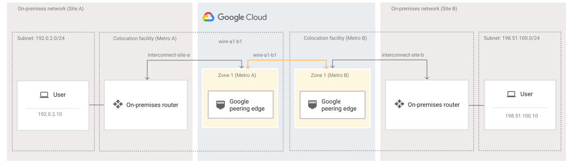](https://docs.cloud.google.com/static/network-connectivity/docs/interconnect/images/single-interconnect-cross-site.svg) Cross-Site Interconnect connections (click to enlarge).
For the basic setup shown in the diagram, a Cross-Site Interconnect
connection is provisioned at each site between Google's network and the
on-premises router in a common colocation facility. Your setup might be
different if your on-premises router isn't in the same colocation facility
as your Cross-Site Interconnect connection.
You can use these connections to create cross-site networks between your
sites.
> [!NOTE]
> **Note:** Cross-Site Interconnect connections don't support adding [VLAN attachments](https://docs.cloud.google.com/network-connectivity/docs/interconnect/how-to/dedicated/creating-vlan-attachments). To connect your on-premises network to VPC networks in Google Cloud by using VLAN attachments, use [Dedicated Interconnect](https://docs.cloud.google.com/network-connectivity/docs/interconnect/concepts/dedicated-overview).
### Components
Cross-Site Interconnect uses the following components to connect
your on-premises networks to each other:
| Component | Description |
|---|---|
| Cross-Site Interconnect connections | The physical connections between Google and your on-premises network sites. A connection exists in a colocation facility where your on-premises network and Google's network meet. You create separate Cross-Site Interconnect connections for each on-premises network site. |
| Wires | Individual wires transport layer 2 traffic between Cross-Site Interconnect connections. Wires belong to a wire group. |
| Wire group | Defines the configuration of the wires that connect Cross-Site Interconnect connections. Wire groups belong to a cross-site network. A wire group has the following key properties: - **Wire group mode** : the traffic mode that the wire group uses, either port or VLAN. For more information, see [Traffic modes](https://docs.cloud.google.com/network-connectivity/docs/interconnect/concepts/cross-site-overview#modes). - **Bandwidth** : the bandwidth for each wire in the group. For more information, see [Wire bandwidth](https://docs.cloud.google.com/network-connectivity/docs/interconnect/concepts/cross-site-overview#bandwidth). |
| Cross-site network | A container for logically grouping related wire groups together. Represents the network that connects your on-premises network sites to each other over Cross-Site Interconnect connections. |
### Traffic modes
The following table describes the traffic modes that Cross-Site Interconnect supports. The traffic mode is a setting
of a wire group.
| Traffic mode | Description |
|---|---|
| Port mode | Port mode lets you send all traffic to the same destination regardless of any VLAN tags that are present, which simplifies the configuration but limits you to one wire per connection. Port mode also supports failure detection. When you enable failure detection, Google Cloud continuously monitors each wire and disables a wire if it loses connectivity so that you can failover to an alternate path, such as another healthy wire in the group. |
| VLAN mode | VLAN mode lets you create multiple virtual networks (VLANs) on a single connection. You can use VLAN tags to isolate and prioritize traffic for enhanced security and flexibility. VLAN tags must be the same for both endpoints of a wire. |
### Wire bandwidth
You configure wire bandwidth, in Gbps, by using the *unmetered bandwidth*
setting when creating a wire group.
Consider the following when setting the unmetered bandwidth:
| Property | Description |
|---|---|
| Bandwidth allocation per wire | The unmetered bandwidth that you configure when creating a wire group applies to each wire in the group. Consider an example in which you have a wire group with a bandwidth setting of 10 Gbps, and both wires in the group support 10 Gbps of bandwidth. Ensure that your bandwidth usage doesn't exceed the capacity of an individual wire. In the preceding example, maintaining a bandwidth usage of less than 10 Gbps helps to avoid packet loss by ensuring sufficient capacity in a failover scenario. |
| Quotas and limits | The following quotas and limits apply to wire bandwidth: - The quota for *Wire groups unmetered bandwidth per Cloud Interconnect metro pair* - The limit for the *Maximum bandwidth per wire* - The limit for the *Maximum bandwidth per traffic flow on a wire* - For more information, see [Quotas and limits](https://docs.cloud.google.com/network-connectivity/docs/interconnect/quotas). - You must check these quotas and limits before you begin provisioning Cross-Site Interconnect as described in [Check bandwidth quotas and limits](https://docs.cloud.google.com/network-connectivity/docs/interconnect/how-to/cross-site/check-bandwidth-quota). |
| Connection capacity | You must ensure that the sum of unmetered bandwidth across all wires that use the same Cross-Site Interconnect connection is less than or equal to the capacity of the connection. Google Cloud doesn't return an error if the connection is over provisioned. |
| Bandwidth per direction | Bandwidth is measured separately for each direction of traffic. For example, consider a wire group with 10 Gbps of unmetered bandwidth. Traffic from metro A to metro B has 10 Gbps of bandwidth, and traffic from metro B to metro A has a separate 10 Gbps of bandwidth. |
## MTU
The MTU for Cross-Site Interconnect is 9000 bytes. This value
isn't configurable, and it covers the entire L2 frame except for the frame
check sequence (FCS).
## Encryption options
The following encryption options are available depending on the wire group mode:
- For wire groups in VLAN mode, you can use MACsec for Cloud Interconnect to help
you secure traffic on Cross-Site Interconnect connections, specifically between your on-premises router and Google's edge routers.
For more information, see
[MACsec for Cloud Interconnect overview](https://docs.cloud.google.com/network-connectivity/docs/interconnect/concepts/macsec-overview).
All Cross-Site Interconnect connections are MACsec capable.
- For wire groups in port mode, you can implement end-to-end encryption between
your on-premises routers by using a protocol of your choice. However, this configuration might introduce a large flow that can't be load balanced. Keep
in mind that your traffic is subject to the limit for *Maximum bandwidth per traffic flow on a wire* . For more information, see [Limits](https://docs.cloud.google.com/network-connectivity/docs/interconnect/quotas#limits).
Regardless of which option you choose, you can still use other higher-level
network security protocols, such as Internet Protocol Security (IPsec) and
Transport Layer Security (TLS).
## Port capacity
For Cross-Site Interconnect, physical connections are available
in two sizes: 10 Gbps or 100 Gbps.
## Provisioning
To provision Cross-Site Interconnect, you
start by deciding where you want Cross-Site Interconnect
connections and checking that you have the necessary quota. Then, you order Cross-Site Interconnect connections
for each site that you want to connect so that Google can allocate the necessary resources and send you a Letter of Authorization
and Connecting Facility Assignment (LOA-CFA). After you receive the LOA-CFA, you
need to submit it to your vendor so that they can provision the connections
between Google's network and your network.
You then need to configure and test the connections with Google before you can
use them. After the connections are ready, you can create a cross-site network
over the connections.
For detailed steps to provision Cross-Site Interconnect, see the
[Cross-Site Interconnect provisioning overview](https://docs.cloud.google.com/network-connectivity/docs/interconnect/how-to/cross-site/provisioning-overview).
> [!NOTE]
> **Note:** If you encounter any issues during the provisioning stage, we advise you to reply directly to the email received with your [LOA-CFA](https://docs.cloud.google.com/network-connectivity/docs/interconnect/concepts/terminology#loa). Replying to that email lets you receive support faster than creating a support case.
## Pricing
For information about pricing, see
[Cloud Interconnect pricing](https://cloud.google.com/network-connectivity/pricing).
## How wire groups work
This section describes how wire groups work in cross-site networks.
The availability SLA depends on the geographic locations that you are
connecting. To view SLA details for each metro pair, see
[Cross-Site Interconnect SLA availability](https://docs.cloud.google.com/network-connectivity/docs/interconnect/concepts/cross-site-locations#metro-sla).
Wire groups include the following resources and settings:
- Four Cross-Site Interconnect connections, two
connections in one metropolitan area (metro) and two connections in another
metro. Connections that are in the same metro must be placed in *different*
[edge availability domains](https://docs.cloud.google.com/network-connectivity/docs/interconnect/concepts/terminology#edge-availability-domain)
(metro availability zones).
If the connections don't meet the preceding requirements, Google Cloud
returns an error when you attempt to create a wire group over the connections.
- Two wires between the connections, with one wire connecting one pair
of corresponding availability zones in each metro and another wire
connecting the other pair of corresponding availability zones.
#### Example configuration
The following example configuration shows four Cross-Site Interconnect
connections in two different metros and different edge availability domains:
`ord-zone1-7`, `ord-zone2-7`, `iad-zone1-1`, and `iad-zone2-1`. There is
one wire between `ord-zone1-7` and `iad-zone1-1`, and another wire between
`ord-zone2-7` and `iad-zone2-1`.
[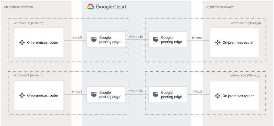](https://docs.cloud.google.com/static/network-connectivity/docs/interconnect/images/redundant-topology.svg) A wire group's topology (click to enlarge).
## Network topologies
While a given wire group can only connect two sites, you can create a cross-site network that connects more than two sites by adding multiple wire groups. This
section describes example configurations for connecting three sites: *Site A* ,
*Site B* , and *Site C*.
If you configure wire groups in VLAN mode, you can use the same
Cross-Site Interconnect connections to create multiple wire groups.
### Hub and spoke topology
The following example configuration shows a basic hub and spoke topology that
includes three sites. In this topology, Site B is the hub and Sites A and C are spokes.
This example configuration includes the following:
- One wire group between Site A and Site B
- One wire group between Site B and Site C
You can add more spokes to this topology by adding a wire group between
Site B and each additional site that you want to connect.
[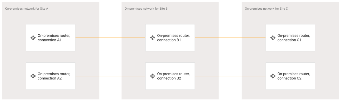](https://docs.cloud.google.com/static/network-connectivity/docs/interconnect/images/hub-spoke-topology.svg) A hub and spoke topology that connects three sites (click to enlarge).
### Ring topology
The following example configuration shows a ring topology that connects three
sites directly with each other. This example configuration includes the
following:
- One wire group between Site A and Site B
- One wire group between Site B and Site C
- One wire group between Site A and Site C
[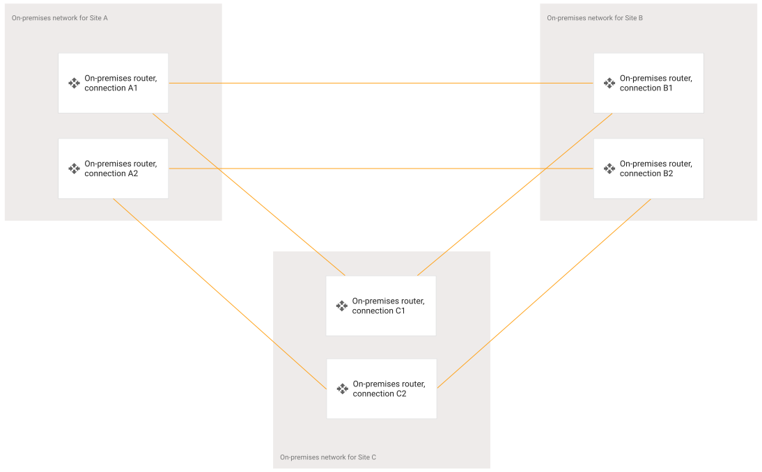](https://docs.cloud.google.com/static/network-connectivity/docs/interconnect/images/ring-topology.svg) A ring topology that connects three sites (click to enlarge).
## What's next
- [See colocation facilities for Cross-Site Interconnect](https://docs.cloud.google.com/network-connectivity/docs/interconnect/concepts/cross-site-locations)
- [Get an overview of provisioning Cross-Site Interconnect](https://docs.cloud.google.com/network-connectivity/docs/interconnect/how-to/cross-site/provisioning-overview)