Bundled load balancing lets you run the load balancers for your
Google Distributed Cloud cluster on the cluster nodes themselves. Keepalived and
HAProxy serve the control plane virtual IP address (VIP), and MetalLB in Layer 2
mode provides data plane load balancing for Services of type `LoadBalancer`.
The load balancers can run on the control plane nodes or on a dedicated load
balancer node pool. You can also run the control plane and data plane load
balancers on separate nodes.
For examples of supported load balancing topologies, see
[Overview of load balancers](https://docs.cloud.google.com/kubernetes-engine/distributed-cloud/bare-metal/docs/installing/load-balance.md.txt).
## Requirements
- All load balancer nodes must be in the same Layer 2 subnet.
- All VIPs must be in the load balancer nodes subnet and be routable through the subnet's gateway.
- The gateway of the load balancer subnet must listen to gratuitous ARP messages and forward ARP packets to the load balancer nodes.
## Configuration fields
Edit the `cluster.spec.loadBalancer` section of the cluster configuration file
to configure bundled load balancing. For information about cluster
configuration files and examples of valid configurations, see one of the
following pages:
- [Create admin clusters](https://docs.cloud.google.com/kubernetes-engine/distributed-cloud/bare-metal/docs/installing/creating-clusters/admin-cluster-creation.md.txt)
- [Create user clusters](https://docs.cloud.google.com/kubernetes-engine/distributed-cloud/bare-metal/docs/installing/creating-clusters/user-cluster-creation.md.txt)
- [Create hybrid clusters](https://docs.cloud.google.com/kubernetes-engine/distributed-cloud/bare-metal/docs/installing/creating-clusters/hybrid-cluster-creation.md.txt)
- [Create standalone clusters](https://docs.cloud.google.com/kubernetes-engine/distributed-cloud/bare-metal/docs/installing/creating-clusters/standalone-cluster-creation.md.txt)
### loadBalancer.mode
This value must be `bundled` to enable bundled load balancing.
### loadBalancer.ports.controlPlaneLBPort
This value specifies the destination port to be used for traffic sent to the
Kubernetes control plane (the Kubernetes API servers).
### loadBalancer.vips.controlPlaneVIP
This value specifies the destination IP address to be used for traffic sent to
the Kubernetes control plane (the Kubernetes API servers). This IP address must
be in the same Layer 2 subnet as the nodes in the cluster. **Don't** list this
address in the [`address pools`](https://docs.cloud.google.com/kubernetes-engine/distributed-cloud/bare-metal/docs/installing/bundled-lb.md.txt#address-pools) section of the configuration
file.
### loadBalancer.vips.ingressVIP
This value specifies the IP address to be used for Services behind the load
balancer for ingress traffic. This field is not allowed in [admin
cluster](https://docs.cloud.google.com/kubernetes-engine/distributed-cloud/bare-metal/docs/installing/creating-clusters/admin-cluster-creation)
configuration files. This address must be listed in the [address
pools](https://docs.cloud.google.com/kubernetes-engine/distributed-cloud/bare-metal/docs/installing/bundled-lb#address-pools) section of the configuration.
### loadBalancer.addressPools
This section of the configuration contains one or more address pools. Each
address pool specifies a list of IP address ranges. When you create a
[Service of type `LoadBalancer`](https://kubernetes.io/docs/concepts/services-networking/service/#loadbalancer),
the external IP addresses for the Service are chosen from these ranges.
> [!NOTE]
> **Note:** Starting with Google Distributed Cloud version 1.16.0, you can update an existing load balancer address pool at any time to change the following two fields: `avoidBuggyIPs` and `manualAssign`.
Address pools are specified in the following format:
```yaml
- name: POOL_NAME
avoidBuggyIPs: BOOLEAN
manualAssign: BOOLEAN
addresses:
- IP_RANGE
- IP_RANGE2
```
- **`name`** : The name of the address pool, **pool-name**, for your own organizational purposes. This field is immutable.
- **`avoidBuggyIPs`** : (Optional) `true` or `false`. If `true`, the pool omits IP addresses ending in `.0` and `.255`. Some network hardware drops traffic to these special addresses. You can omit this field, its default value is `false`. This field is mutable.
- **`manualAssign`** : (Optional) `true` or `false`. If `true`, addresses in this pool are not automatically assigned to Kubernetes Services. If `true`, an IP address in this pool is used only when it is specified explicitly by a service. You can omit this field, its default value is `false`. This field is mutable.
- **`addresses`** A list of one or more nonoverlapping IP address ranges. ip-range can be specified in either CIDR notation (like `198.51.100.0/24`) or range notation (like `198.51.100.0-198.51.100.10`, with no spaces around the dash). This field is immutable.
The IP address ranges in the `addresses` list must not overlap and must be in
the same subnet as the nodes running load balancers.
### loadBalancer.nodePoolSpec
This section of the configuration specifies a list of nodes to run load
balancers on. Load balancer nodes can run regular workloads by default; there is
no special taint on those nodes. Although nodes in the load balancer node pool
can run workloads, they're separate from the nodes in the worker node pools. You
can't include a given cluster node in more than one node pool. Overlapping node
IP addresses between node pools block cluster creation and other cluster
operations.
If you want to prevent workloads from running on a node in the load balancer
node pool, add the following taint to the node:
```yaml
node-role.kubernetes.io/load-balancer:NoSchedule
```
Google Distributed Cloud adds tolerations for this taint to the pods that are required
for load balancing.
The following example shows a load balancing node pool with two nodes. The first
node has a standard IP address `nodePoolSpec.nodes.address` ('1.2.3.4') and a
Kubernetes IP address `nodePoolSpec.nodes.k8sIP` (`10.0.0.32`). When you specify
the optional `k8sIP` address for a node, it's dedicated to handling data traffic
for the node, such as requests and responses for the Kubernetes API, the
kubelet, and workloads. In this case, the standard IP address
`nodePoolSpec.nodes.address` is used for SSH connections to the node for
administrative cluster operations. If you don't specify a `k8sIP` address, the
standard node IP address handles all traffic for the node.
```yaml
nodePoolSpec:
nodes:
- address: 1.2.3.4
k8sIP: 10.0.0.32
- address: 10.0.0.33
```
By default, all nodes in the load balancer node pool must be in the same Layer 2
subnet as the load balancer VIPs configured in the
[`loadBalancer.addressPools`](https://docs.cloud.google.com/kubernetes-engine/distributed-cloud/bare-metal/docs/installing/bundled-lb.md.txt#address-pools) section of the configuration file.
However, if you specify a Kubernetes IP address `k8sIP` for a node, only that
address needs to be in the same Layer 2 subnet as the other load balancer VIPs.
If `nodePoolSpec` isn't set, the bundled load balancers run on the control
plane nodes. We recommend you run load balancers on separate node pools if
possible.
## Control plane load balancing
The control plane load balancer serves the control plane virtual IP address
(VIP). Google Distributed Cloud runs Keepalived and HAProxy as Kubernetes static pods on
the load-balancer nodes to announce the control plane VIP. Keepalived uses the
Virtual Router Redundancy Protocol (VRRP) on the load balancer nodes for high
availability.
## Data plane load balancing
> [!NOTE]
> **Note:** MetalLB in BGP mode isn't supported. For load balancing in BGP mode, see [Configure bundled load balancers with BGP](https://docs.cloud.google.com/kubernetes-engine/distributed-cloud/bare-metal/docs/how-to/lb-bundled-bgp.md.txt).
The data plane load balancer is for all Kubernetes Services of type
[`LoadBalancer`](https://docs.cloud.google.com/kubernetes-engine/docs/concepts/service.md.txt#services_of_type_loadbalancer).
Google Distributed Cloud uses [MetalLB](https://metallb.universe.tf/)
running in Layer 2 mode for data plane load balancing. Data plane load balancing
can only be configured through Google Distributed Cloud, don't modify the MetalLB
ConfigMap directly. You can use all MetalLB features including
[IP address sharing across Services](https://metallb.universe.tf/usage/#ip-address-sharing).
See the MetalLB documentation for feature information.
MetalLB runs a speaker Pod on each node using a daemonset, using
[memberlist](https://github.com/hashicorp/memberlist/blob/master/README.md)
for high availability. There is a MetalLB dedicated load balancer node for each
Kubernetes Service, rather than one for the entire cluster. This way traffic is
distributed across load balancer nodes if there are multiple Services.
The data plane load balancers can run on either the control plane nodes
or on a subset of worker nodes. Bundling data plane load balancers on the
control plane nodes increases utilization of the control plane nodes.
Additionally, bundling on the control plane nodes also increases the risk of
overloading the control plane and increases the risk profile of confidential
information on the control plane, such as SSH keys.
## Load balancer separation
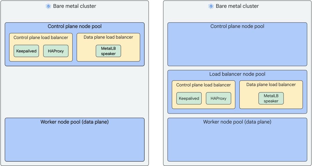
Prior to release 1.32, when you configure Layer 2 load balancing with MetalLB,
the control plane load balancers and the data plane load balancers run on the
same nodes. Depending on your configuration, the load balancers all run on the
control plane nodes or they all run in the load balancer node pool.
The following diagram shows the default bundled load balancer configuration with
both control plane and data plane load balancers running on control plane nodes
or both running in the load balancer node pool:
With version 1.32 clusters, you can configure the control plane load balancers
to run on the control plane nodes and the data plane load balancers to run in
the load balancer node pool. You can specify this separation of load balancers
when you create a new version 1.32 cluster, or you can update a version 1.32
cluster to migrate the data plane load balancers from the control plane nodes to
the load balancer node pool.
The cluster configuration for separated load balancers should look similar to
the following example:
```yaml
apiVersion: baremetal.cluster.gke.io/v1
kind: Cluster
metadata:
name: hybrid-ha-lb
namespace: cluster-hybrid-ha-lb
spec:
type: hybrid
profile: default
anthosBareMetalVersion: 1.36
gkeConnect:
projectID: project-fleetcontrolPlane:
loadBalancer:
mode: bundled
nodePoolSpec:
nodes:
- address: 10.200.0.2
- address: 10.200.0.3
- address: 10.200.0.4
clusterNetwork:
pods:
cidrBlocks:
- 192.168.0.0/16
services:
cidrBlocks:
- 10.96.0.0/20
...loadBalancer:
mode: bundled
...nodePoolSpec:
nodes:
- address: 10.200.0.5
- address: 10.200.0.6
- address: 10.200.0.7
clusterOperations:
...
```
#### Separate load balancers when creating a cluster
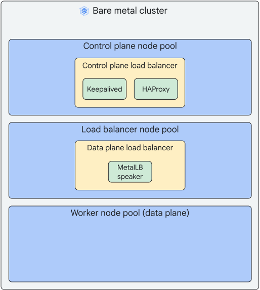
If you're creating a new version 1.32 or higher cluster, you can configure the
load balancers to run the control plane load balancers on the control plane
nodes and the data plane load balancers on the load balancer node pool.
The following diagram shows the control plane and data plane load balancers
separated on to different nodes:
To separate the load balancers when you create a cluster, use the following
steps:
1. In the cluster configuration file, specify a load balancer node pool with
`loadBalancer.nodePoolSpec` as described in the
[`loadBalancer.nodePoolSpec`](https://docs.cloud.google.com/kubernetes-engine/distributed-cloud/bare-metal/docs/installing/bundled-lb.md.txt#loadbalancernodepoolspec) section of this
document.
2. Add [`controlPlane.loadBalancer.mode`](https://docs.cloud.google.com/kubernetes-engine/distributed-cloud/bare-metal/docs/reference/cluster-config-ref.md.txt#controlplane-loadbalancer-mode)
to the cluster configuration file and set the `mode` value to `bundled`.
3. Finish configuring your cluster and run `bmctl create cluster` to create the
cluster.
#### Migrate data plane load balancers off of the control plane
If you have an existing version 1.32 or higher cluster where neither
`controlPlane.loadBalancer.mode` nor `loadBalancer.nodePoolSpec` is set, both
the control plane load balancer and the data plane load balancer run in the
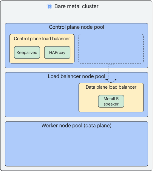
control plane node pool. You can update the cluster to migrate the data plane
load balancer to a load balancer node pool.
The following diagram shows the control plane and data plane load balancers
separated after the data plane load balancer has been migrated off of the
control plane nodes:
To migrate the data plane load balancer to a load balancer node pool when you
update a cluster, use the following steps:
1. In the cluster configuration file, specify a load balancer node pool with
`loadBalancer.nodePoolSpec` as described in the
[`loadBalancer.nodePoolSpec`](https://docs.cloud.google.com/kubernetes-engine/distributed-cloud/bare-metal/docs/installing/bundled-lb.md.txt#loadbalancernodepoolspec) section of this
document.
2. Add [`controlPlane.loadBalancer.mode`](https://docs.cloud.google.com/kubernetes-engine/distributed-cloud/bare-metal/docs/reference/cluster-config-ref.md.txt#controlplane-loadbalancer-mode)
to the cluster configuration file and set the `mode` value to `bundled`.
3. Update the cluster by running the following command:
```bash
bmctl update cluster -c CLUSTER_NAME --kubeconfig=ADMIN_KUBECONFIG
```
Replace the following:
- `CLUSTER_NAME`: the name of the cluster you're
updating.
- `ADMIN_KUBECONFIG`: the path of the admin cluster
kubeconfig file.
## Preserving client source IP address
The `LoadBalancer` Service created with the bundled Layer 2 load balancing
solution uses the default `Cluster` setting for the external traffic policy.
This setting, `spec.externalTrafficPolicy: Cluster`, routes external traffic to
cluster-wide endpoints, but it also obscures the client source IP address.
Google Distributed Cloud supports two methods for [preserving the client source IP
address](https://kubernetes.io/docs/tasks/access-application-cluster/create-external-load-balancer/#preserving-the-client-source-ip):
- Set the forwarding mode for load balancing to Direct Server Return (DSR).
For more information about DSR forwarding mode, including
instructions to enable it, see [Configure load balancing forwarding mode](https://docs.cloud.google.com/kubernetes-engine/distributed-cloud/bare-metal/docs/how-to/lb-network-mode.md.txt).
- Set the external traffic policy to local for the `LoadBalancer` Service and
configure related Services and Ingress accordingly. The following sections
describe how to configure your cluster to use this method.
### `LoadBalancer` Services
When using `externalTrafficPolicy: Local` in your `LoadBalancer` Services, set
your application pods to run exactly on the load balancer nodes. Add the
following `nodeSelector` to your application pods to make this change:
```yaml
apiVersion: v1
kind: Pod
...
spec:nodeSelector:
baremetal.cluster.gke.io/lbnode: "true"
...
```
### `NodePort` Services
Kubernetes does source network address translation (SNAT) for `NodePort`
Services. To retain the client source IP addresses, set
`service.spec.externalTrafficPolicy` to `Local`. Kubernetes won't perform SNAT
anymore, but you must make sure there are pods running exactly on the node IP
you picked.
### Ingress
If your applications are HTTP services, you can achieve client IP visibility
by configuring ingress components:
1. Open the `istio-ingress` Service for editing:
```bash
kubectl edit service -n gke-system istio-ingress
```
2. Add `externalTrafficPolicy: Local` to the `spec`, save and exit the
editor.
```yaml
apiVersion: v1
kind: Service
...
spec:
...externalTrafficPolicy: Local
```
3. Open the `istio-ingress` Deployment for editing:
```bash
kubectl edit deployment -n gke-system istio-ingress
```
4. Add the following `nodeSelector` to the Deployment, save and exit the
editor.
```yaml
apiVersion: apps/v1
kind: Deployment
...
spec:
...
template:
...
spec:
...nodeSelector:
baremetal.cluster.gke.io/lbnode: "true"
...
```
Now, all of your services behind Ingress see a `X-Forwarded-For` header with the
client IP, like the following example:
X-Forwarded-For: 21.0.104.4